
Process for separation of at least one metal sulfide from a mixed sulfide ore or concentrate

a technology of mixed sulfide ore and concentrate, which is applied in the field of metal ores or concentrates, can solve the problems that known metallurgical processes do not provide satisfactory metal sulfide separation from such ores and concentrates

Active Publication Date: 2018-04-26
GOLDCORP
View PDF0 Cites 6 Cited by
  • Summary
  • Abstract
  • Description
  • Claims
  • Application Information

AI Technical Summary

Benefits of technology

[0144]In understanding the scope of the present application, the term “comprising” and its derivatives, as used herein, are intended to be open ended terms that specify the presence of the stated features, elements, components, groups, integers, and / or steps, but do not exclude the presence of other unstated features, elements, components, groups, integers and / or steps. The foregoing also applies to words having similar meanings such as the terms, “including”, “having” and their derivatives. It will be understood that any aspects described as “comprising” certain components may also “consist of” or “consist essentially of,” wherein “consisting of” has a closed-ended or restrictive meaning and “consisting essentially of” means including the components specified but excluding other components except for materials present as impurities, unavoidable materials present as a result of processes used to provide the components, and components added for a purpose other than achieving the technical effect of the invention.
[0145]Terms of degree such as “about” and “approximately” as used herein mean a reasonable amount of deviation of the modified term such that the end result is not significantly changed. These terms of degree should be construed as including a deviation of at least ±5% of the modified term if this deviation would not negate the meaning of the word it modifies.
[0146]When introducing elements disclosed herein, the articles “a”, “an” and “the” are intended to mean that there are one or more of the elements.
[0147]The above disclosure generally describes the present invention. A more complete understanding can be obtained by reference to the following specific Examples. The Examples are described solely for purposes of illustration and are not intended to limit the scope of the invention. Changes in form and substitution of equivalents are contemplated as circumstances may suggest or render expedient. Although specific terms have been employed herein, such terms are intended in a descriptive sense and not for purposes of limitation.EXAMPLES

Problems solved by technology

Known metallurgical processes do not provide satisfactory metal sulfide separation from such ores and concentrates.

Method used


Image

  • Process for separation of at least one metal sulfide from a mixed sulfide ore or concentrate
  • Process for separation of at least one metal sulfide from a mixed sulfide ore or concentrate
  • Process for separation of at least one metal sulfide from a mixed sulfide ore or concentrate

Examples


example 1

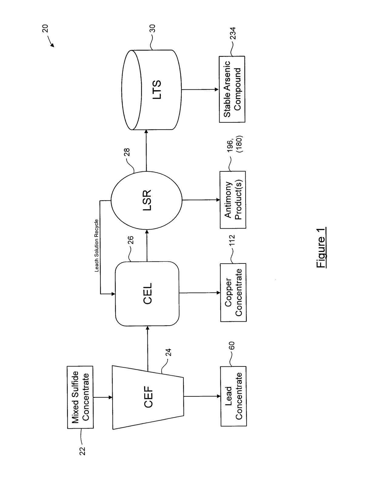
[0148]In Examples 1 to 3, “locked cycle” flotation tests were performed to evaluate the removal and separation efficiency of arsenic and antimony containing sulfosalts from the mixed sulfide concentrate.

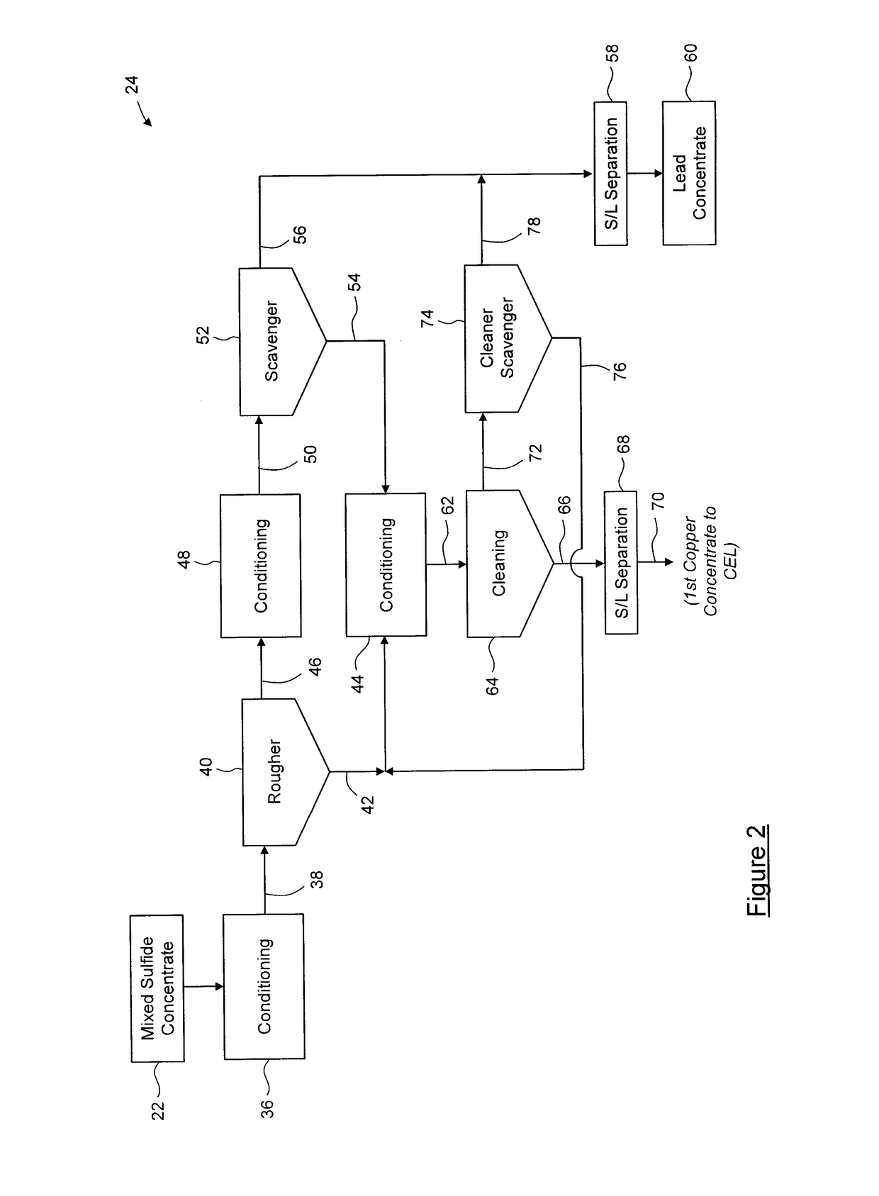
[0149]In this example, the test was performed on a high copper feed concentrate using four locked cycles with a rougher and three stages of cleaning. The collector was a thiocarbamate (Aero A5100), the depressant was sodium metabisulfite (SMBS), and the dispersant was a caustic starch solution.

[0150]The results of the test are shown in Table 1. About 89% of the lead reported to the lead concentrate, while about 80% of the copper, about 82% of the arsenic and about 91% of the antimony reported to the copper concentrate.

TABLE 1Mass,Cu,As,Sb,Pb,Assays%%%%%Pb-Cu bulk conc.10030.08.37.924.2Cu conc.6338.511.014.73.9Pb conc.3715.74.12.351.8Distribution, %—CuAsSbPbPb-Cu bulk conc.100100100100100Cu conc.6380829111Pb conc.372018989

example 2

[0151]In this example, a “locked cycle” flotation test was performed on a lower copper feed concentrate than the concentrate of Example 1, using six locked cycles with a rougher and three stages of cleaning. In this example, the collector was Aero A5100, the depressant was SMBS, and the dispersant was a caustic starch solution.

[0152]The results of this test are shown in Table 2. About 99% of the lead reported to the lead concentrate, while about 78% of the copper, about 84% of the arsenic and about 74% of the antimony reported to the copper concentrate.

TABLE 2Mass,Cu,As,Sb,Pb,Assays%%%%%Pb-Cu bulk conc.1006.51.11.857.8Cu conc.1435.47.512.63.6Pb conc.861.70.20.767.3Distribution, %—CuAsSbPbPb-Cu bulk conc.10010100100100Cu conc.147884741Pb conc.8622162699

example 3

[0153]In this example, a “locked cycle” flotation test was performed on a similar feed material to Example 2, using six locked cycles with a rougher and three stages of cleaning. In this example, the collector was Aero A5100, the depressant was ammonium bisulfite, and the dispersant was a caustic starch solution.

[0154]The results of this test are shown in Table 3. About 97% of the lead reported to the lead concentrate, while about 84% of the copper, about 86% of the arsenic and about 81% of the antimony reported to the copper concentrate.

TABLE 3Mass,Cu,As,Sb,Pb,Assays%%%%%Pb-Cu bulk conc.1006.31.23.756.2Cu conc.1927.95.515.49.4Pb conc.811.20.20.862.3Distribution, %—CuAsSbPbPb-Cu bulk conc.100100100100100Cu conc.198486813Pb conc.8116141997


PUM

PropertyMeasurementUnit
concentrationaaaaaaaaaa

Abstract

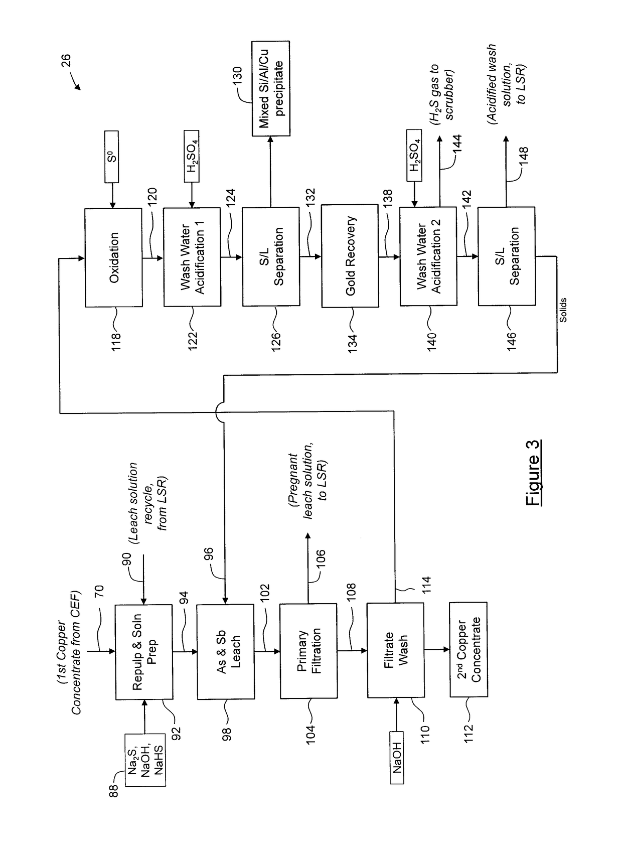
A stabilization process for an arsenic solution comprising thiosulfates, the process comprising: acidifying the arsenic solution to decompose the thiosulfates, to yield an acidified solution; oxidizing the acidified solution to oxidize residual As3+ to As5+ and reduced sulfur species to sulfates, to yield a slurry comprising elemental sulfur; separating elemental sulfur from the slurry to yield a liquid; oxidizing the liquid to oxidize residual reduced sulfur species, to yield an oxidized solution; and forming a stable arsenic compound from the oxidized solution.

Description

CROSS-REFERENCE TO RELATED APPLICATIONS[0001]The present application is a divisional application of U.S. patent application Ser. No. 15 / 115,142, filed on Jul. 28, 2016, which is a national stage application of PCT Patent Application No. PCT / CA2015 / 000050, filed Jan. 30, 2015, which claims priority to U.S. Provisional Patent Application Ser. No. 61 / 934,193, filed Jan. 31, 2014, the contents of each of which are hereby incorporated by reference in their entireties.BACKGROUND OF THE DISCLOSURE1. Field of the Disclosure[0002]The subject application relates generally to processing of metal ores or concentrates, and in particular to a process for separation of at least one metal sulfide from such ores or concentrates.2. Description of the Related Art[0003]Metallurgical processes are applied to metal ore deposits and such processes can be categorized into three general areas: leaching, solution concentration and purification, and metal recovery.[0004]Such processes have been previously des...

Claims


Application Information

Patent Timeline
Patent Type & Authority Applications(United States)
IPC IPC(8): C22B3/44C22B13/00B03D1/002C22B15/00B03D1/02C22B30/02C22B3/00B03D1/012C22B30/04C22B3/04C22B1/00C22B11/00
CPCC22B13/00B03D1/002Y02P10/234B03D2201/005C22B15/00B03D1/02C22B30/02C22B3/44C22B15/0065B03D2201/04C22B13/04B03D1/012B03D2201/02B03D2203/02C22B30/04C22B3/04C22B1/00C22B11/00Y02P10/20C01G28/02C01G30/008C01G30/00
Inventor TOMLINSON, MARCUSMARTINEZ, TEODOROHILLE, SIMON
Owner GOLDCORP
Learn More