Otdr using an electro-absorption modulator for both pulse forming and pulse detection

a technology of electro-absorption modulator and pulse detection, applied in the field of fiberoptic communication, can solve the problems of large amount of light to be reflected back, inability to achieve perfect absorption-free transmission of optical transmission fiber, and detectors temporarily blinded or saturated, so as to reduce maintenance and logistics costs for operators, the effect of effective determining the length of the dead zon

Active Publication Date: 2018-04-26
XIEON NETWORKS SARL
View PDF13 Cites 1 Cited by
  • Summary
  • Abstract
  • Description
  • Claims
  • Application Information

AI Technical Summary

Benefits of technology

[0026]In a preferred embodiment of the invention, the control unit is configured for switching off the light source an offset time after switching the modulation voltage back to the first range of values, wherein the offset time preferably is between 10 ns and 100 ns. Said offset time corresponds to the time during which sampling light continues to be emitted into the waveguide of the electro-absorption modulator and hence during which a photocurrent due to sampling light is generated between the electrodes thereof. Thus, the duration of said offset time determines the time during which a photocurrent due to a reflected light puls...

Problems solved by technology

On the one hand, no optical transmission fiber provides perfect absorption-free transmission.
On the other hand, when a light pulse travelling in the fiber hits an abrupt medium transition, like for example a connector, a mechanical splice or a fiber breakage, the consequent abrupt change in the index of refraction causes a large amount of light to be reflected back.
As commonly known in the art, when a high amount of light is reflected back and received at the detector, the detector is temporarily blinded or saturated.
Having the shortest-possible dead zone is a highly relevant issue in the field of fiber-optic communication.
For example, when testing in the premises of dense optical networks, dead zones which are not short enough might lead to various junction points or connectors being missed and not identified by the technicians, which makes it harder to locate potential problems.
Manufacturers hence usually struggle to provide OTDRs able to operate with very short pulses so as to provide for shorter dead zones.
A side effe...

Method used


Image

  • Otdr using an electro-absorption modulator for both pulse forming and pulse detection
  • Otdr using an electro-absorption modulator for both pulse forming and pulse detection
  • Otdr using an electro-absorption modulator for both pulse forming and pulse detection

Examples


Embodiment Construction

[0040]For the purposes of promoting an understanding of the principles of the invention, reference will now be made to a preferred embodiment illustrated in the drawings, and specific language will be used to describe the same. It will nevertheless be understood that no limitation of the scope of the invention is thereby intended, such alterations and further modifications in the illustrated apparatus and such further applications of the principles of the invention as illustrated therein being contemplated as would normally occur now or in the future to one skilled in the art to which the invention relates.

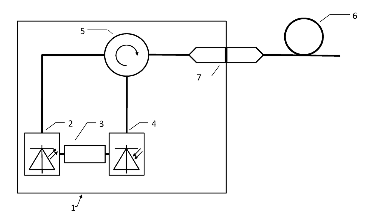
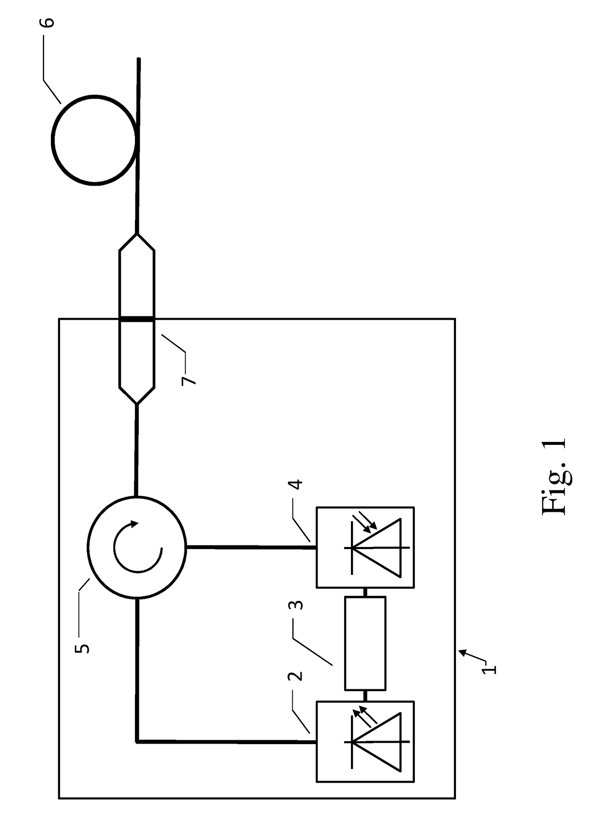
[0041]FIG. 1 shows a schematic representation of a conventional OTDR 1 comprising a light-emitting device 2 and a light detection device 4. The light-emitting device 2 is configured for emitting sampling light pulses into the optical transmission fiber 6 via a connector 7. The sampling light pulses pass through the circulator 5 and are reflected at an irregularity in the optical t...


PUM


Abstract

An optical time domain reflectometer for determining properties of an optical transmission fiber, the optical time domain reflectometer comprising an electro-absorption modulator comprising a waveguide and two electrodes, wherein the waveguide is arranged between the electrodes, a light source configured for emitting sampling light into the waveguide, wherein the waveguide is connected or to be connected between the fiber and the light source, and a control unit for controlling the operation of the light source and a modulation voltage between the electrodes. The electro-absorption modulator is capable of assuming an absorption state, wherein the electro-absorption modulator is further configured for receiving reflected light pulses resulting from the reflection of the pulses of sampling light in the fiber, wherein the absorption of reflected light pulses in the electro-absorption modulator results in the creation of a photocurrent between the electrodes.

Description

PRIORITY INFORMATION[0001]This application claims priority to and the benefit of European Patent Application No. 16194825.2, filed in the European Patent Office on Oct. 20, 2016, the entire contents of which are incorporated herein by reference.FIELD OF THE INVENTION[0002]The present invention is in the field of fiber-optic communication. In particular, the present invention relates to an optical time domain reflectometer (OTDR) for determining properties of an optical transmission fiber and to a corresponding method of determining properties of an optical transmission fiber using an OTDR.BACKGROUND OF THE INVENTION[0003]OTDRs are used in the field of fiber-optic communication to gain insight into the main optical parameters of an optical transmission fiber, like information regarding fiber attenuation, and to detect impairments or irregularities, like deteriorated connectors or fiber breakages. An OTDR typically comprises a light-emitting device and a light detecting device. The li...

Claims


Application Information

Patent Timeline
IPC IPC(8): G01M11/00
CPCG01M11/3145G01M11/3109
Inventor FRICKE, ANDREAS
Owner XIEON NETWORKS SARL
Why Eureka
Try Eureka