Remotely powered line monitor

a monitor and remote control technology, applied in the direction of electromagentic field characteristics, measurement devices, instruments, etc., can solve the problems of large voltage requirements to produce significant frequency or delay changes, blind distribution portion of power grid, and almost no real-time data available to grid operators, etc., to achieve the effect of improving performance characteristics

Active Publication Date: 2018-04-26
SENSANNA
View PDF16 Cites 15 Cited by
  • Summary
  • Abstract
  • Description
  • Claims
  • Application Information

AI Technical Summary

Benefits of technology

[0022]The present invention provides physical embodiments of a line monitoring unit with aspects that produce beneficial operation over prior art, and teaches field probe embodiments that have improved performance characteristics over prior art, including probes to detect electric field and separate probes to detect magnetic field. In addition, the present invention provides for monitoring systems and system components, including several preferred circuit configurations that interface one or more electric and / or magnetic field probes with SAW sensor-tag devices to enable wireless measurement of the field probe voltages. Select preferred embodiments incorporate protective circuit elements for suppression of transient voltage surges.

Problems solved by technology

However, the voltages required to produce significant changes in frequency or delay were large (hundreds of volts to kV) for realistic die thicknesses.
The distribution portion of the power grid runs essentially blind today, i.e., almost no real-time data is available to the grid operator on the condition of the distribution lines and transformers.
Pinging smart meters can provide data on power outages at the individual meter level, but automated diagnostic tools that inform operators about the details, locations, and causes of outages are not available.
Equally concerning, there are no prognostic tools for the grid that can predict component failures prior to problems occurring.
However, there are no current methods for distributed monitoring of the grid that are low enough cost to enable widespread monitoring, particularly at the local distribution level.
The use of realistic diodes for input signal routing, however, impacts the performance of this approach, in that most real diodes have non-zero threshold voltages (VTH) that can be as much as 0.7V (typically).
The zero voltage crossing point of the input signal also can become difficult to track due to the diode threshold voltage.

Method used


Image

  • Remotely powered line monitor
  • Remotely powered line monitor
  • Remotely powered line monitor

Examples


Embodiment Construction

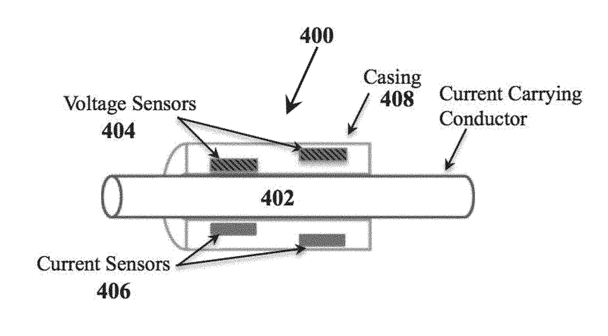
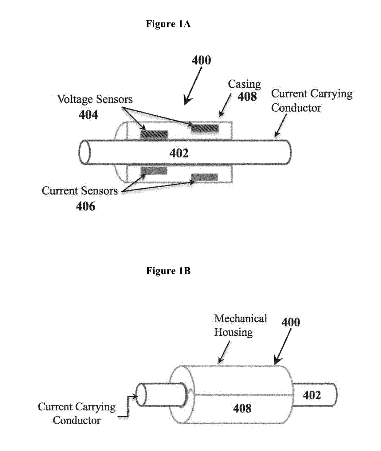
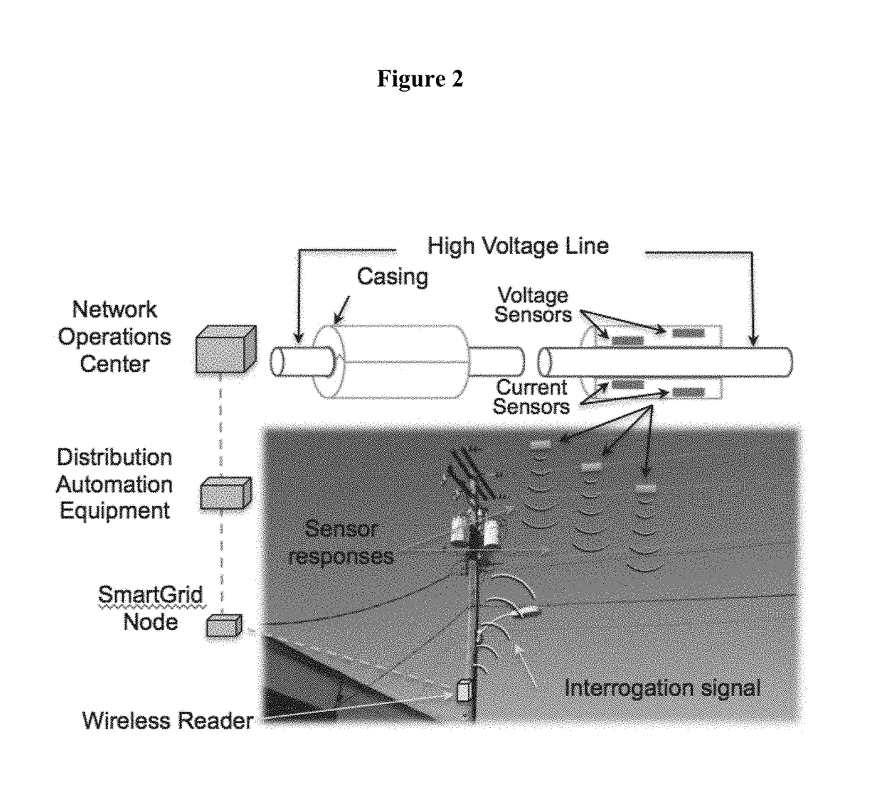
[0056]The present invention teaches improved devices, apparatuses, systems, and methods involving the use of field probes with voltage-controlled variable impedance elements and surface-launched acoustic wave devices, including surface acoustic wave (SAW) devices and SAW sensor-tag wireless interface devices to measure voltage and current in current carrying conductors (CCCs) via measurement of the electric fields and magnetic fields around said CCCs. The devices, apparatuses, systems, and methods taught in the present invention include a remotely powered line-mounted measurement unit that requires no connection to electrical ground for operation, and that has no internal energy source, no energy harvesting or power conditioning circuitry, no discrete energy storage components, and no radio. Hence, it is referred to as a ‘remotely powered’ unit, as the radio signal incident on the unit activates the measurement devices, which respond with device identification information and measur...


PUM


Abstract

Improved devices, apparatuses, systems, and methods involving the use of field probes with voltage-controlled variable impedance elements and surface-launched acoustic wave devices, including surface acoustic wave (SAW) devices and SAW sensor-tag wireless interface devices to measure voltage and current in current carrying conductors (CCCs) via measurement of the electric fields and magnetic fields around said CCCs are disclosed. The devices, apparatuses, systems, and methods taught in the present invention include a remotely powered line-mounted measurement unit that requires no connection to electrical ground for operation, and that has no internal energy source, no energy harvesting or power conditioning circuitry, no discrete energy storage components, and no radio. The devices, apparatuses, systems, and methods taught in the present invention also provide for determining the phase (leading or lagging) of the current relative to the voltage in AC power systems, and also provide for measurement of temperature of the conductor.

Description

STATEMENT REGARDING FEDERALLY SPONSORED RESEARCH OR DEVELOPMENT[0001]This invention was made with government support under contract DE-EE0007195 awarded by the Department of Energy (DOE). The government has certain rights in the invention.BACKGROUND OF THE INVENTIONField of the Invention[0002]The field of the present invention relates to devices, apparatuses, systems, and methods used to measure the voltage, current, temperature, and other properties of current carrying conductors (CCCs). More specifically, the present invention relates to the use of field probes with voltage-controlled variable impedance elements and surface-launched acoustic wave devices, including surface acoustic wave (SAW) sensor-tag wireless interface devices, to measure voltage and current in current CCCs via measurement of the electric fields and magnetic fields around said CCCs. The devices, apparatuses, systems, and methods taught in the present invention include a remotely powered line-mounted measurement...

Claims


Application Information

Patent Timeline
Patent Type & Authority Applications(United States)
IPC IPC(8): G01R29/08
CPCG01R29/08G01R15/144G01R15/148G01R29/0878
Inventor HINES, JACQUELINE H.HINES, ANDREW T.YANEY, DAVID S.KIRKPATRICK, DOUG
Owner SENSANNA
Why Eureka
Try Eureka