Methods for treating bitumen mixtures

a bitumen mixture and treatment method technology, applied in the direction of working up pitch/asphalt/bitumen by mixing fractions, separation processes, fuels, etc., can solve the problems of lack of specific combinations of steps and features of prior methods and apparatus, and achieve the desired initial boiling point (ibp), avoid acid corrosion attacks, advantageously avoid

Inactive Publication Date: 2018-05-03
USD GRP LLC
View PDF2 Cites 1 Cited by
  • Summary
  • Abstract
  • Description
  • Claims
  • Application Information

AI Technical Summary

Benefits of technology

[0011]Yet another unexpected benefit of using a fractionating temperature of 450 F (232 C) and below is that the heavy fraction, and also the resulting high-viscosity bitumen composition that is subsequently directed to the railcar, can have a desirable initial boiling point (IBP). In a preferred embodiment, where a fractionating temperature of 450 F (232 C) or less is used, the resulting heavy fraction preferably has an initial boiling point (IBP) of 298 F (148 C) (ASTM D86) or higher. That initial boiling point is sufficiently high to avoid a “hazardous” classification under applicable regulations, which state that a hazardous commodity is one that has an initial boiling point (IBP) that is less than 95 F (35 C) (ASTM D86).
[0012]Another unexpected benefit of operating at a fractionation temperature of no more than 450 F is that in addition to the heavy fraction and light fraction having the desired flammability and combustibility properties (i.e., such that they are non-hazardous), undue cracking of the heavier hydrocarbon components present in the low-viscosity bitumen composition is minimized or even avoided. In certain specific embodiments, a fractionating temperature above 450 F (232 C) can be used, but the fractionating temperature should not reach a point where substantial cracking of the heavier hydrocarbon components takes place. Thus, for certain bitumen compositions where flash point is not a concern a fractionating temperature of up to 455 F, or 460 F, or 465 F, or 470 F, or 475 F, or 480 F, or 485 F, or 490 F, or 500 F, or 505 F, or 510 F, or 515 F, or 520 F, or 525 F, or 530 F, or 535 F, or 540 F, or 545 F, or 550 F may be used.
[0013]Yet another unexpected benefit of operating the fractionator at temperatures at 450 F (232 C) and below is avoidance of acid corrosion attacks on the column, piping systems and heat exchangers. It has been discovered that such acid corrosion attacks would otherwise be triggered as a result of the naphthenic acid contained in the low-viscosity bitumen composition existing at a particular temperature above 450 F (232 C). Such acid corrosion attacks can be devastating to fractionating equipment or at minimum can be detrimental to the mechanical integrity of such equipment, and can be advantageously avoided by limiting the fractionating temperature as stated herein.
[0014]Moreover, another unexpected benefit of limiting the fractionation temperature to no greater than 450 F (232 C) is that salt dissociation is minimized and in some cases avoided entirely. Consequently, the fractionating can advantageously be performed without the need to engage in de-salting, which could require substantial amounts of fresh water and also associated waste water disposal procedures. Thus, certain methods disclosed herein provide unexpected environmental benefits associated with using a fractionating temperature of up to 450 F (232 C). At that fractionating temperature and below, any minor salt dissociation and potential associated corrosion can be easily treated with anti-corrosion additives combined with an overhead water wash system to maintain the overhead condensing system. However, the amount of water required using the identified fractionation temperature is minimal when compared to the amount of water that would be required with more than insubstantial salt dissociation.
[0015]Yet another benefit of using a fractionating temperature of 450 F (232 C) and below is that the temperature of the heavy fraction exits the fractionator at a temperature that can be conveniently adjusted downward to 212 F (100 C) or below, before the heavy fraction enters the railcar as a high-viscosity bitumen composition with desirable non-hazardous temperature properties. Specifically, for example, heat can be transferred away from the both the heavy fraction and the light fraction exiting the fractionator and to the low-viscosity bitumen composition entering the fractionator, using cross-flow heat exchange, and a person having ordinary skill in the art will be familiar with heat exchangers that are commercially available for that purpose. For example, low-viscosity bitumen may leave the pipeline at 60 F and enter a storage tank where it is maintained at approximately 60 F. The low-viscosity bitumen composition may then be directed through a conduit toward the fractionator, but first enters a shell-and-tube heat exchanger where it makes heat exchange contact with the heavy fraction that is exiting the fractionator at a temperature of (for example) 210 F), so that the temperature of the low-viscosity bitumen composition could be raised from 60 F to 135 F while the temperature of the heavy fraction could be lowered from 210 F to 145. Then, the low-viscosity bitumen composition may be passed through another shell-and-tube heat exchanger where it makes heat exchange contact with the light fraction that could be exiting the fractionator at a temperature of (for example) 396 F, which could result in the temperature of the low-viscosity bitumen composition being raised from 135 F to 267 F, and the temperature of the light fraction being lowered from 396 F to 250 F. Of course, those temperatures are approximate only and would change depending on a number of factors including the type and configuration of the heat exchangers as well as the compositions of the different streams. Also, depending on the fractionation temperature and other factors, the temperature of the heavy fraction exiting the fractionator may have a temperature ranging from 220 F (104 C) to 300 F (149 C), and can be efficiently and economically lowered to a desirable temperature of 212 F (100 C) or less using cross-flow heat exchange with the incoming cold high-viscosity bitumen as described above. Accordingly, a substantial amount of heat can be removed from the heavy fraction by heat transfer through the walls of steel piping through which the heavy fraction passes en route to a storage facility prior to transfer to a railcar. In addition, artificial chilling can be included to supplement the heat transfer via the walls of the steel piping. This allows the cooled heavy fraction to be safely loaded into the railcars meeting the non-hazardous regulations.
[0016]The low-viscosity bitumen composition is preferably preheated, e.g., using cross-flow heat exchange, even before being directed to a fired heater that raises the temperature to a maximum of 450 F after which time it is fed to the fractionator. As used herein, the fired heater may in certain embodiments be considered part of the fractionator even where it is physically outside of the fractionating column. By pre-heating, e.g., using heat transfer from the heavy and light fractions, the amount of fuel required for the fired heater is less than the amount of fuel without pre-heating, which also lowers the overall emissions from the system.

Problems solved by technology
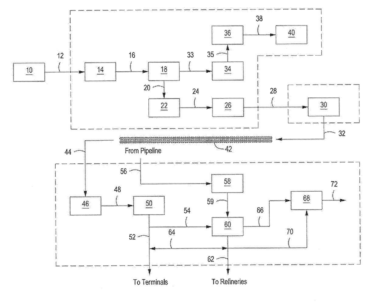
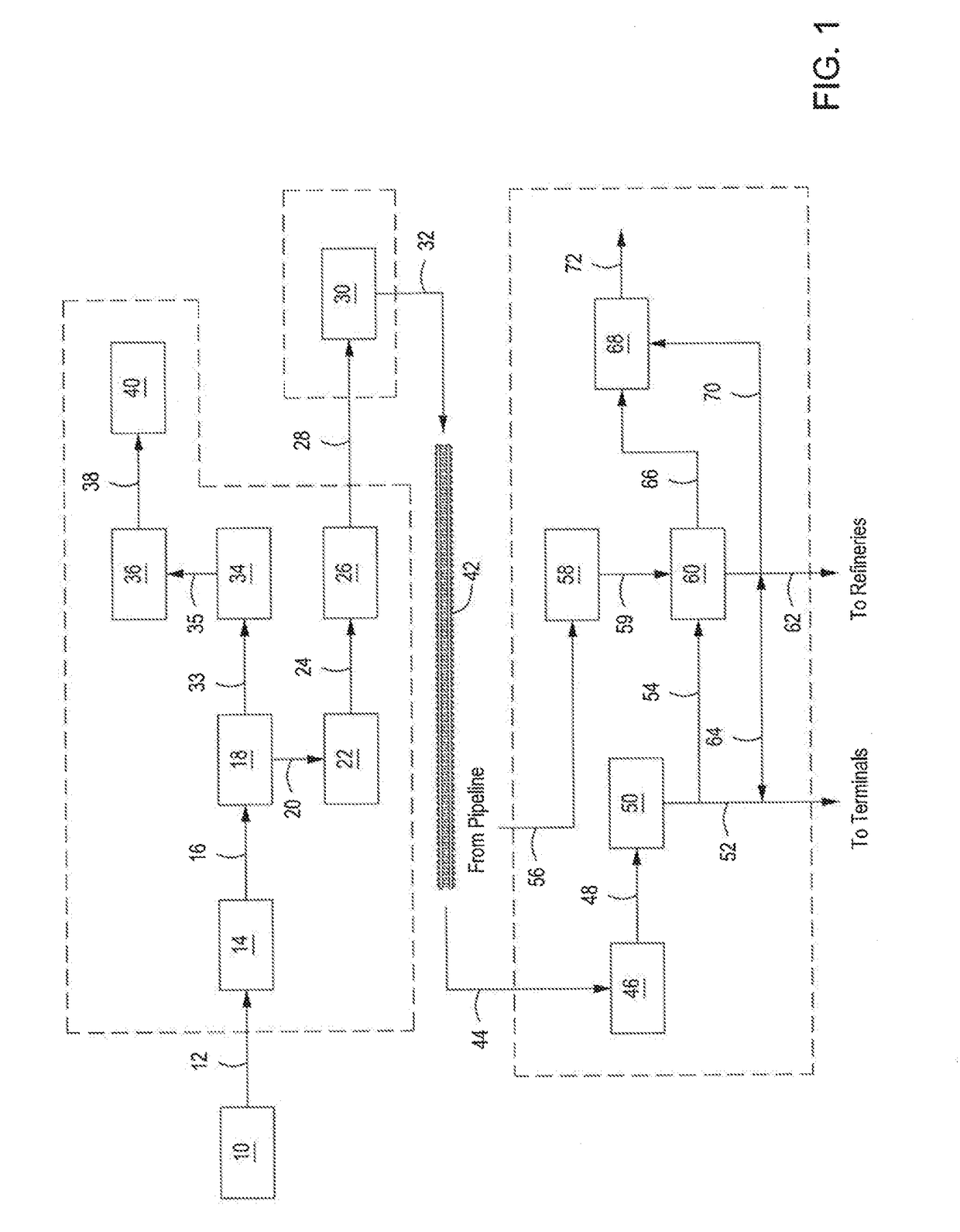
However, it is contemplated that those prior methods and apparatus lack the specific combinations of steps and features described as being part of certain methods and apparatus herein.
Also, certain methods and apparatus described have benefits that would be surprising and unexpected to a person of ordinary skill in the art who is familiar with the prior art existing at the time of inventions claimed herein but without the benefit of the disclosure herein.

Method used


Image

  • Methods for treating bitumen mixtures
  • Methods for treating bitumen mixtures
  • Methods for treating bitumen mixtures

Examples


examples

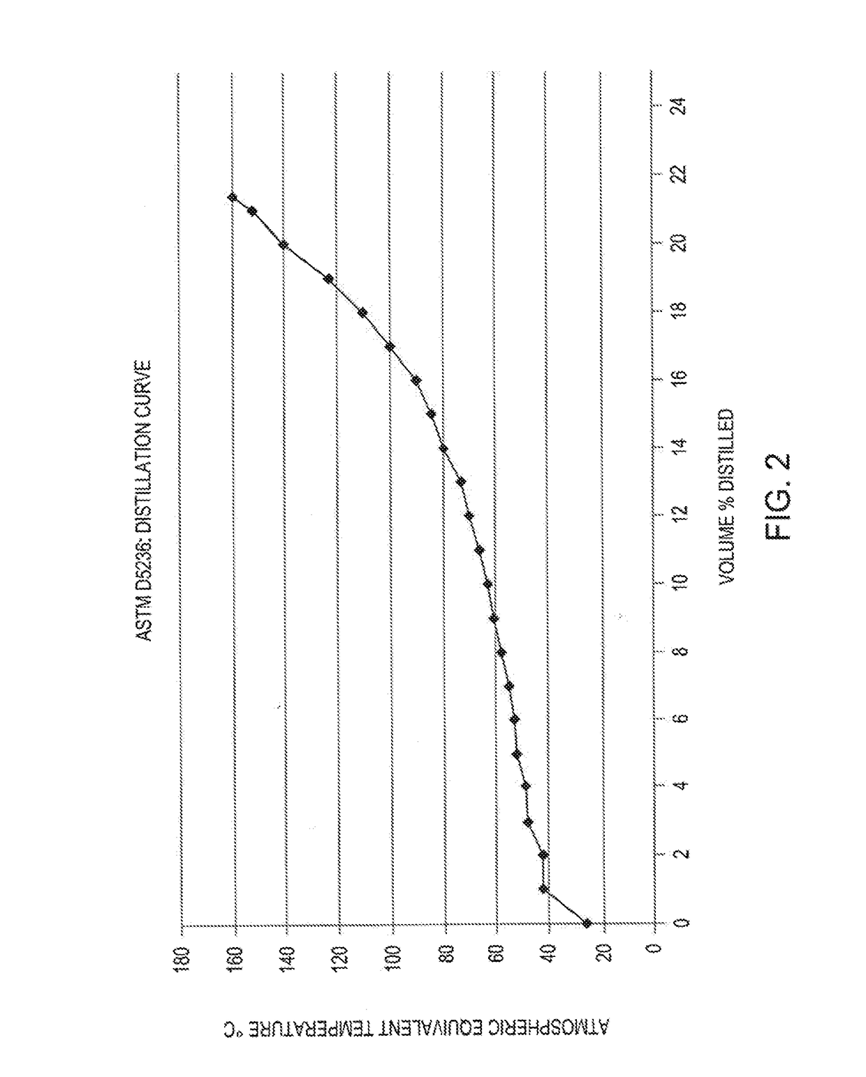
[0103]A sample of Suncor Cold Lake dilbit (CLD) was obtained from storage tank inventory and evaluated for physical properties, including light ends composition and extended liquid hydrocarbon atmospheric analysis. To simulate one or more of the methods described herein, a pot still distillation apparatus was operated over a predetermined series of runs under atmospheric conditions to strip out specific light ends from the dilbit at successively higher boiling points (FBP ranging from 50° C. to 160° C.). The resulting heavy fractions were then tested for Flash Point and Initial Boiling Point using ASTM methodology as discussed below.

[0104]Results substantiated that by removing from the CLD dilbit sample the particular light ends with boiling points (FBP) ranging up to 160° C., the resulting heavy fraction had an Initial Boiling Point (IBP) of 234.8° C. (using ASTM D86) and Flash Points of 103° C. and 113° C. (using ASTM D93 and ASTM D3828 methods, respectively).

[0105]The analytical ...


PUM

PropertyMeasurementUnit
densityaaaaaaaaaa
absolute pressureaaaaaaaaaa
densityaaaaaaaaaa

Abstract

Disclosed are methods for preparing a high-viscosity non-hazardous bitumen composition for transportation in a railcar, wherein the method may include: (a) providing to a fractionator system a low-viscosity bitumen composition previously residing in a pipeline having a first viscosity and comprising a miscible blend of hydrocarbons, which blend was prepared by mixing a first diluent composition with a first bitumen composition; (b) heating the low-viscosity bitumen composition in the fractionator system at an operating temperature of from 170 C to 232 C to provide a first light fraction and a first heavy fraction; (c) removing at least a portion of the first heavy fraction from the fractionator system, wherein the first heavy fraction has a second viscosity that is higher than the first viscosity; (d) forming a high-viscosity non-hazardous bitumen composition from at least a portion of the first heavy fraction; and (e) directing the high-viscosity non-hazardous bitumen composition to a railcar.

Description

BACKGROUND1. Field of Inventions[0001]The field of the inventions disclosed and / or claimed in this application and any resulting patent is the treatment of bitumen mixtures including particularly a type of bitumen composition known as “dilbit.”2. Description of Related Art[0002]Dilbit is a composition made by mixing bitumen with diluent. Sufficient diluent is added to the bitumen so that the resulting bitumen composition has a viscosity low enough so that it may be easily transported through a pipeline. Thus the term dilbit as used herein means any blend resulting from the mixing of diluent and bitumen in an amount sufficient to lower the viscosity of the bitumen so that it can flow through a pipeline. In the past, various methods and apparatus have been disclosed, proposed, and used for treating dilbit including the methods and apparatus disclosed in the references appearing on the face of this patent, e.g., earlier patents and publications. However, it is contemplated that those p...

Claims


Application Information

Patent Timeline
Patent Type & Authority Applications(United States)
IPC IPC(8): C10G7/00C10C3/00C10C3/06C10L1/16B01D3/32B01D3/34
CPCC10G7/00C10C3/005C10C3/06C10L1/1616B01D3/32B01D3/34C10G2300/302C10G2300/308C10G2300/4006B01D2251/208B01D2257/304B01D3/143
Inventor BERG, STUARTHOWERTON, AMANDALEMAIRE, MARKNALL, ROBERT
Owner USD GRP LLC
Why Eureka
Try Eureka