DRC Processing Tool For Early Stage IC Layout Designs

a drc processing and early-stage technology, applied in the field of drc software tools, can solve the problems of ic designer/sellers missing important market windows, long process, and inability to meet the requirements of early-stage drc processing, and achieve the effect of maximizing the number of rules checks, improving the quality of drc processing, and facilitating the processing of early-stage dr

Active Publication Date: 2018-05-03
SYNOPSYS INC
View PDF40 Cites 21 Cited by
  • Summary
  • Abstract
  • Description
  • Claims
  • Application Information

AI Technical Summary

Benefits of technology

[0010]The present invention is directed to improved design rule checking (DRC) tools and associated methodologies that enhance DRC processing of early-stage (dirty) IC layout designs by way of utilizing one or more novel processing techniques (features) including automatically recognizing and eliminating/marking problematic cell placements and automatically arranging the order of rule check operations prior to DRC processing, limiting DRC processing to a predetermined time limit or predetermined number of errors, and generating error reports in both textual and intuitive graphics-based formats. Automatically recognizing problematic cells involves identifying cells that have suspect placement (e.g., overlapping cells) during pre-DRC hierarchy processing. The problematic cells are then either eliminated from the design layout workspace or marked for DRC processing only after DRC processing of all non-problematic cells is completed within preset time/error budget constraints, thereby focusing DRC processing on selected regions (i.e., cells) of a dirty IC layout design that are most likely to provide useful error information (i.e., maximizing the number of rules checks performed) within a minimal DRC processing runtime. Automatically ordering the number of rule checks performed during DRC processing involves sequentially performing rule checks based on predetermined criteria in order to provide maximum useful DRC error results in a minimum amount of time. For example, automatic ordering may involve arranging the rule checks based on anticipated rule execution time, where rules that execute relatively quickly are ranked higher than those that require longer execution times), whereby a maximum number of error checks are performed within a predetermined time period. Limiting the DRC processing session to a predetermined amount of time or number of detected errors facilitates providing a user with a manageable amount of error data within a predictable amount of time, which in turn facilitates faster DRC signoff. Finally, automatically providing error data in both textual and graphical forms (e.g., using a contrasting dots “heat map” to depict the X-Y locations of rule violations) provides the intuitive presentation of relevant problem areas of a dirty IC layout design that are easily identified for correction by a human user, and non-relevant areas (e.g., missing block regions) can be efficiently identified and ignored, thereby facilitating the generation of a modified layout design that can be used to fabricate a desired IC device. Implementing one or more of these novel processing techniques in the improved DRC tools of the present invention facilitates efficient correction of layout errors appearing in each early-stage “dirty” IC layout design iteration as the IC layout design progresses toward signoff by way of eliminating previously verified “known-good” cells and/or unchanged layers from incremental DRC processing, thereby significantly reducing overall DRC processing time and, as a result, overall manufacturing costs of IC devices that are subsequently fabricated using masks (reticles) produced in accordance with the finished IC layout design.
[0011]According to an embodiment of the invention, an improved DRC tool efficiently produces useful DRC error results by way of automatically setting the rule runset order utilized during DRC rule check processing (rule checking operations) in a way that optimizes or maximizes the number of rule checks that are performed in a fixed amount of time, and terminates the DRC process after either a predetermined time limit is reached or a predetermined number of rule violations are detected. In one embodiment, automatically setting the order of DRC rule execution involves assigning a rank value to each rule provided in a DRC rule deck based on an anticipated rule execution time duration of each rule (e.g., based on a number of procedures performed by each rule), then performs DRC processing by sequentially rule checking each cell in the design layout workspace based on the established rule runset order (e.g., with rule check processing performed using rules having the shortest execution time durations before rule check processing is performed using rules having longer execution time duration). In addition to automatically selecting the DRC rule execution order, the duration of the rule check process is limited by either (a) a predetermined maximum processing time period, or (b) a predetermined maximum number of rule violations. A benefit of limiting rule check time is that this approach optimizes the generation of useful error data in a predictable reasonable amount of time (e.g., three hours) by way of first performing the largest possible number of short-duration (“inexpensive”) or more-relevant rule checks, and performing “expensive” or less relevant rule checks later in the DRC processing only if the predetermined time limit has not been reached. A benefit of limiting rule checking to a limited number of rule violations is that this approach avoids the generation of overwhelming amounts of error data, thereby allowing a user/operator to more efficiently apply corrections that facilitate signoff in a shorter amount of time. By combining rule runset ordering and time/error limiting, the present invention provides a DRC tool that greatly enhances efficient analysis and correction of early-stage IC layout designs.
[0012]According to another embodiment of the invention, the improved DRC tool automatically detects systematic or fundamental layout errors by way of recognizing when a particular DRC rule generates an unusually high rate of rule violations during first-pass rule check processing, and suspends (i.e., postpones or omits) further rule checks using the high-violation-rate-causing rule (i.e., bypasses subsequent cells in the design layout workspace), at least until first...

Problems solved by technology

The development and physical production of an integrated circuit (IC) device is a long, complicated process that typically involves a wide range of design tools and fabrication systems.
The step of committing to manufacturing can very expensive to an IC device designer/seller that pays a fab to produce an IC device based on the designer/seller's IC design; it can cost tens of millions of dollars to commit to build an IC device, and this money is typically lost by the designer/seller when a fabricated device fails to function as intended due to errors in the design layout.
The assurance provided by DRC processing is worth more than just the cost of IC tooling—layout errors discovered during manufacturing can lead to manufacturing delays, which in turn can cause the IC designer/seller to miss important market windows.
The missing/incomplete layout design portions of dirty IC designs occur because complex IC typically comprise multiple interconnected circuit blocks that are generated by different sources (e.g., different blocks may be developed by different design teams in the designer/seller company, and some blocks may be purchased from external licensed sources).
A problem with implementing conventional DRC tools early in the IC design process is that “signoff” DRC tools (e.g., IC Validator produced by the assignee of the present application) have been developed to check every block very precisely, to search for and report every error in the early stage design.
If designs are “dirty” then the signoff DRC tool can run for a very long time and produce gigabytes of data due to unavoidable violations caused by the missing blocks and incomplete connections.
That is, performi...

Method used


Image

  • DRC Processing Tool For Early Stage IC Layout Designs
  • DRC Processing Tool For Early Stage IC Layout Designs
  • DRC Processing Tool For Early Stage IC Layout Designs

Examples


Embodiment Construction

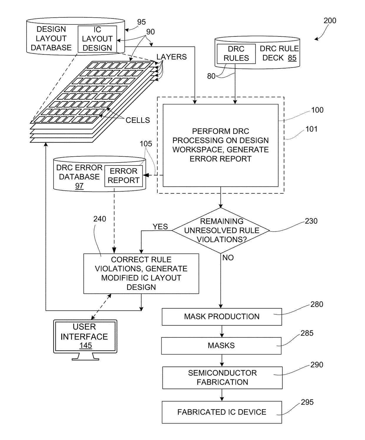
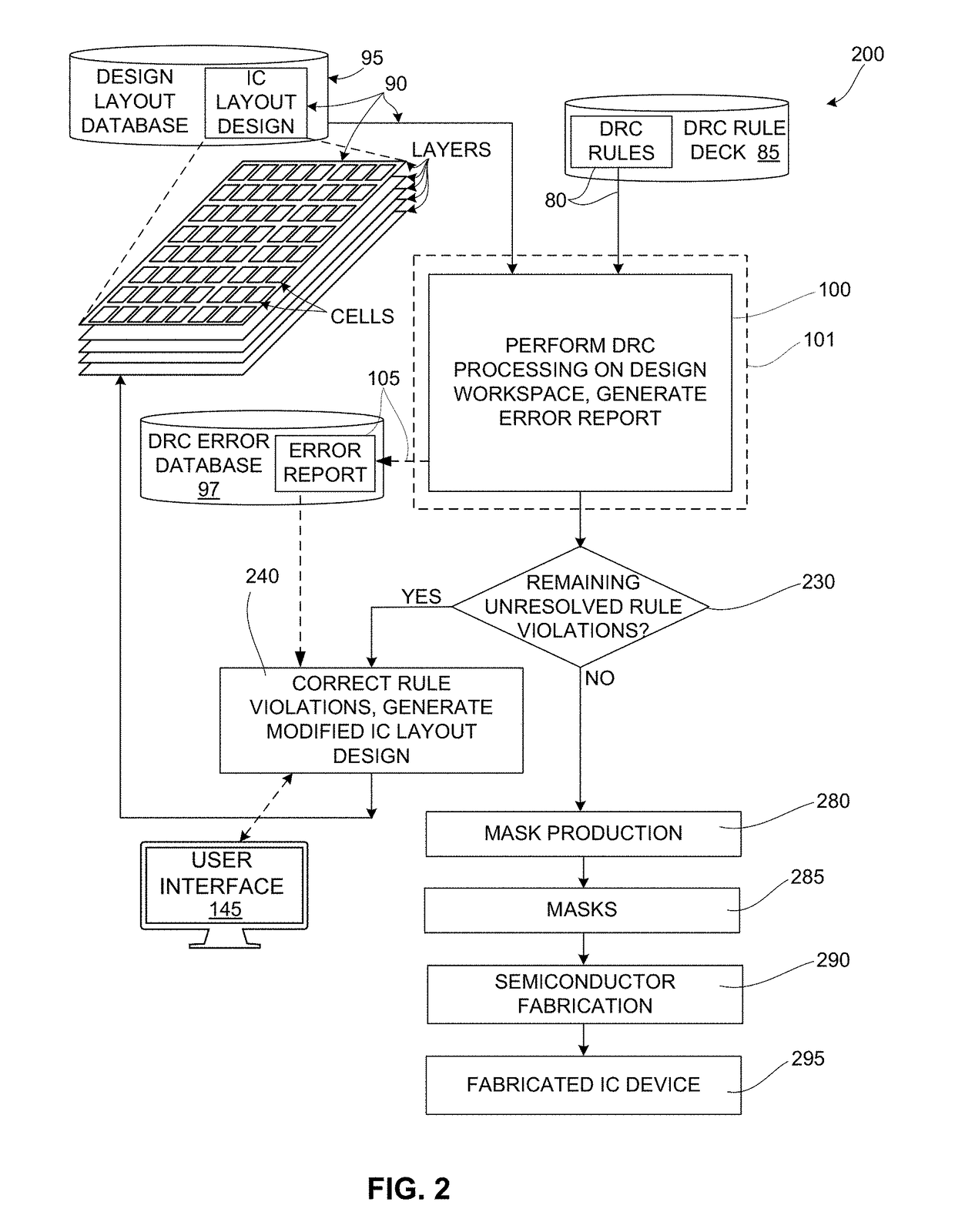
[0031]The present invention is directed to an improved DRC tool that is optimized for efficient DRC processing of early-stage (dirty) IC layout designs. The following description is presented to enable one of ordinary skill in the art to make and use the invention as provided in the context of a particular application and its requirements. In one embodiment the improved DRC tool is generated by way of modifying a conventional signoff-type DRC tool to include one or more of the novel processing techniques to dramatically speed up early-stage DRC processing, such as: automatically terminating the processing of DRC rules that generate large numbers of errors and consume large amounts of machine resources; automatically excluding bad cell placements so they are not checked; automatically determining and running basic DRC rules first and, based on intermediate results, deciding to complete the rest of the DRC rules on all layers, complete the remaining rules on a subset of layers, or com...


PUM


Abstract

A DRC tool optimized for analyzing early-stage (“dirty”) IC layout designs by performing one or more of (a) automatically selectively focusing DRC processing to selected regions (i.e., layers and/or cells) of a dirty IC layout design that are most likely to provide useful error information to a user, (b) automatically selectively ordering and/or limiting rule checks performed during DRC processing to provide the user with a manageable amount of error data in a predetermined reasonable amount of time, and (c) automatically providing error data in a graphical manner using a contrasting dot to indicate the location of each rule violation, whereby relevant problem areas of the dirty IC layout design are easily identified for correction by a human user, and non-relevant areas (e.g., missing block regions) can be efficiently identified and ignored, thereby facilitating efficient modification of the IC layout design.

Description

RELATED APPLICATIONS[0001]This application claims priority from U.S. Provisional patent application 62 / 415,404, entitled “DRC PROCESSING TOOL FOR EARLY STAGE IC LAYOUT DESIGNS”, which was filed on Oct. 31, 2016, and is incorporated by reference herein.BACKGROUND OF THE DISCLOSURE[0002]This disclosure generally relates to design rule checking (DRC) software tools and the methods performed by such tools, and more particularly to DRC tools and methods that are optimized to facilitate efficient DRC processing on early-stage “dirty” IC layout designs.RELATED ART[0003]The development and physical production of an integrated circuit (IC) device is a long, complicated process that typically involves a wide range of design tools and fabrication systems. In designing an integrated circuit (IC) device, engineers typically rely upon computer simulation tools to help create a circuit schematic design consisting of individual devices coupled together to perform a certain function. To actually fab...

Claims


Application Information

Patent Timeline
IPC IPC(8): G06F17/50
CPCG06F17/5081G06F17/30286G06F30/398G06F16/20G06F30/33
Inventor STUDDERS, JOHN R.
Owner SYNOPSYS INC
Why Eureka
Try Eureka