Projection display apparatus

a projection display and display device technology, applied in the direction of picture reproducers using projection devices, instruments, non-linear optics, etc., can solve the problem of reducing the contrast ratio of projected images

Active Publication Date: 2018-05-10
SONY CORP
View PDF2 Cites 7 Cited by
  • Summary
  • Abstract
  • Description
  • Claims
  • Application Information

AI Technical Summary

Benefits of technology

[0008]It is therefore desirable to provide a projection display apparatus that makes it possible to suppress a decrease in a contrast ratio in a projected image.
[0010]In the first projection display apparatus according to the embodiment of the present disclosure, the light in at least one wavelength band selected from the first to third wavelength bands enters the first incident surface of the color separator as the first polarized light, and the light in the other wavelength bands enters the second incident surface of the color separator as second polarized light orthogonal to the first polarized light. This makes it possible to guide light in each of the first to third wavelength bands to corresponding one of the first to third reflective light modulators without using, for example, a retardation film (hereinafter referred to as “narrow band retardation film”) that selectively rotates polarized light in a specific wavelength band selected from the first to third wavelength bands. Alternatively, this makes it possible to reduce the number of such narrow band retardation films. The light in the respective wavelength bands outputted from the first to third reflective light modulators is projected on a projection surface by the projection optical system.
[0012]In the second projection display apparatus according to the embodiment of the present disclosure, the first polarization splitter is disposed to allow the light in the one wavelength band to enter the first incident surface and to allow light in the other two wavelength bands to enter the second incident surface. This makes it possible to guide light in each of the first to third wavelength bands to corresponding one of the first to third reflective light modulators without using, for example, a retardation film (hereinafter referred to as “narrow band retardation film”) that selectively rotates polarized light in a specific wavelength band selected from the first to third wavelength bands. Alternatively, this makes it possible to reduce the number of such narrow band retardation films. The light in the respective wavelength bands outputted from the first to third reflective light modulators is projected on a projection surface by the projection optical system.
[0013]According to the first projection display apparatus of the embodiment of the present disclosure, the light in at least one wavelength band selected from the first to third wavelength band enters the first incident surface of the color separator as the first polarized light, and the light in the other wavelength bands enters the second incident surface of the color separator as the second polarized light. This makes it possible to separate light into the light in the first to third wavelength bands without using the narrow band retardation film and guide light in each of the first to third wavelength bands to corresponding one of the first to third reflective light modulators. Alternatively, this makes it possible to reduce the number of narrow band retardation films. In the narrow band retardation film here, characteristic control is difficult; therefore, in actuality, a polarization direction of light in an unintentional wavelength band (that is, a wavelength band other than wavelength bands to be separated) is also rotated. As a result, light in a wavelength band different from a target wavelength band is leaked into each of reflective light modulators to decrease a contrast ratio in a projected image. Separating light into the light in the first to third wavelength bands without using such a narrow band retardation film or with the reduced number of narrow band retardation films makes it possible to suppress a decrease in the contrast ratio in the projection image.
[0014]According to the second projection display apparatus of the embodiment of the present disclosure, the first polarization splitter is disposed to allow the light in the one wavelength band to enter the first incident surface and to allow the light in the other two wavelength bands to enter the second incident surface. This makes it possible to separate light into the light in the first to third wavelength bands without using the narrow band retardation film and guide the light in each of the first to third wavelength bands to corresponding one of the first to third reflective light modulators. Alternatively, this makes it possible to reduce the number of narrow band retardation films. In the narrow band retardation film here, characteristic control is difficult; therefore, in actuality, a polarization direction of light in an unintentional wavelength band (that is, a wavelength band other than wavelength bands to be separated) is also rotated. As a result, light in a wavelength band different from a target wavelength band is leaked into each of reflective light modulators to decrease a contrast ratio in a projected image. Separating light into the light in the first to third wavelength bands without using such a narrow band retardation film or with the reduced number of narrow band retardation films makes it possible to suppress a decrease in the contrast ratio in the projection image.

Problems solved by technology

However, using the wavelength selective retardation film that rotates a polarization direction of light in a narrow band as described above causes an issue that a contrast ratio in a projected image is decreased.

Method used


Image

  • Projection display apparatus
  • Projection display apparatus
  • Projection display apparatus

Examples


first embodiment

Configuration

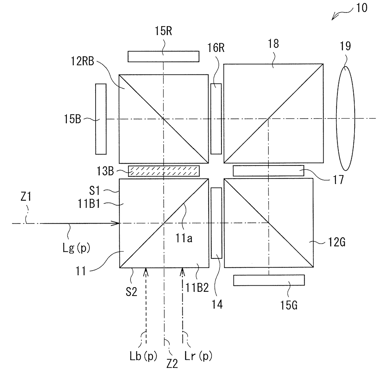
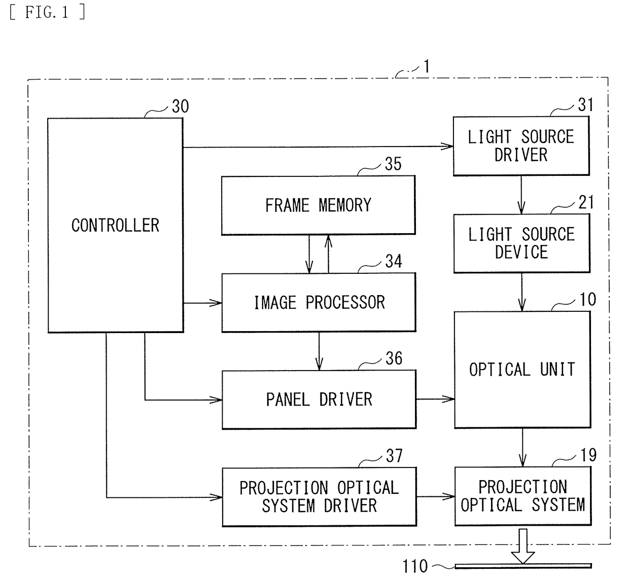
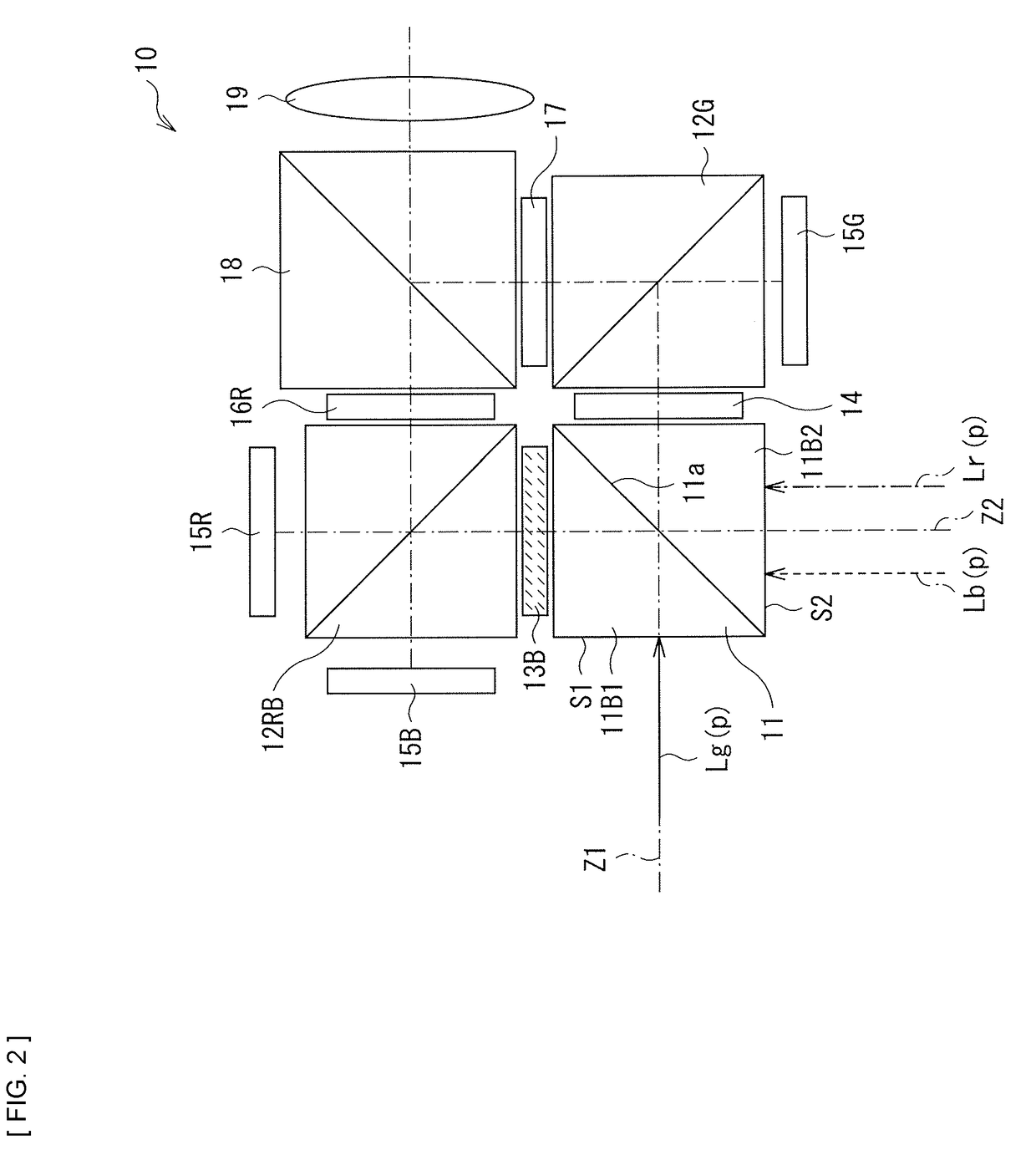
[0045]FIG. 1 is a functional block diagram illustrating an entire configuration of a projection display apparatus (a projection display apparatus 1) according to a first embodiment of the present disclosure. The projection display apparatus 1 is, for example, a display apparatus that projects an image on a screen 110 (a projection surface). The projection display apparatus 1 is coupled to an unillustrated external image supplier via an I / F (interface), and performs projection on the screen 110 on the basis of an image signal inputted to the interface. Examples of the external image supplier include computers such as PCs and various kinds of image players. It is to be noted that a configuration of the projection display apparatus 1 described below is illustrative, and the projection display apparatus of the present disclosure is not limited to such a configuration.

[0046]The projection display apparatus 1 includes, for example, a light source driver 31, a light source dev...

modification example 1-1

[0088]FIG. 10 illustrates a configuration example of an optical unit according to a modification example 1-1. The foregoing embodiment involves an example in which light in the respective wavelength bands enters the incident surfaces S1 and S2 of the polarization splitter 11 as p-polarized light; however, light entering the polarization splitter 11 may be s-polarized light. For example, as with the configuration of the modification example, light Lg(s) in the green band may enter the incident surface S1 of the polarization splitter 11 and light Lr(s) in the red band and light Lb(s) in the blue band may enter the incident surface S2 of the polarization splitter 11.

[0089]In the modification example, each of the light Lr(s) in the red band, the light Lg(s) in the green band, and the light Lb(s) in the blue band is emitted as s-polarized light from the light source. Moreover, a retardation film (corresponding to the retardation film 14 in the foregoing embodiment) is unnecessary between...

modification example 1-2

[0092]FIG. 11 illustrates a configuration example of an optical unit according to a modification example 1-2. In the foregoing embodiment, the light in the green band enters the incident surface S1 of the polarization splitter 11, and the light in the red band and the light in the blue band enter the incident surface S2 of the polarization splitter 11; however, a combination of light in the wavelength bands entering the incident surfaces S1 and S2 is not limited thereto. For example, as with the modification example, the light in the blue band may enter the incident surface S1, and the light in the green band and the light in the red band may enter the incident surface S2.

[0093]In the modification example, each of the light Lr(p) in the red band, the light Lg(p) in the green band, and the light Lb(p) in the blue band is emitted as p-polarized light from the light source. Moreover, a wavelength selective retardation film 13R1 is disposed between the incident surface S2 of the polariz...


PUM


Abstract

A first projection display apparatus includes a color separator (41A) that has first and second incident surfaces (S1a and S1b), and allows light in first to third wavelength bands to pass therethrough or reflects the light in the first to third wavelength bands; first to third reflective light modulators (15); a first polarization splitter (12G); a second polarization splitter (12RB); and a projection optical system (19). Light in at least one of the first to third wavelength bands enters the first incident surface of the color separator as first polarized light, and light in the other wavelength bands enters the second incident surface of the color separator as second polarized light orthogonal to the first polarized light.

Description

TECHNICAL FIELD[0001]The present disclosure relates to a projection display apparatus using, for example, a reflective light modulator.BACKGROUND ART[0002]Projectors (projection display apparatuses) using a reflective liquid crystal display element called LCOS (Liquid Crystal On Silicon) have high resolution. Hence, in recent years, such projectors have become widespread as large-screen display apparatuses. There have been proposed optical systems using the reflective liquid crystal display element and a polarizing beam splitter (PBS) (for example, refer to PTL 1 and PTL 2).[0003]In the optical system disclosed in PTL 1, light is separated by color into light of the three primary colors R (red), G (green), and B (blue), and light of each of the primary colors is guided to a reflective liquid crystal display element corresponding to the color. A retardation film having wavelength selectivity (a wavelength selective retardation film) is used to separate light into the three primary co...

Claims


Application Information

Patent Timeline
Patent Type & Authority Applications(United States)
IPC IPC(8): H04N9/31G03B33/00G03B21/28
CPCH04N9/3197G03B33/00G03B21/28G02B27/1026G02B27/141G02B27/283G03B21/2073G03B33/12G03B21/005H04N9/3105H04N9/3164H04N9/3167G02B27/28G02F1/13G03B21/00G03B21/14
Inventor SATO, YOSHIHISAYANAGISAWA, HIROYUKITANAKA, MASAMIYAO, RYO
Owner SONY CORP
Why Eureka
Try Eureka