
Motor Fibre Neuromodulation

a motor fibre and neuromodulation technology, applied in the field of neuromodulation, can solve the problems of reducing the implanted affecting the physical size and lifetime of the device, and unwanted side effects, so as to reduce the inability to respond to muscle response, increase or commence muscle response, and reduce the effect of inability to respond muscl

Active Publication Date: 2018-05-17
CLOSED LOOP MEDICAL PTY LTD
View PDF7 Cites 60 Cited by
  • Summary
  • Abstract
  • Description
  • Claims
  • Application Information

AI Technical Summary

Benefits of technology

The present invention provides a method for assessing the motor response to neural stimulation by measuring the slow neural response caused by the stimulation. This method can be used during surgery to locate the nerve and optimally position the electrodes. The invention also provides a neurostimulator device and computer software for applying electrical stimuli to a neural pathway and measuring the slow neural response. The slow response can be used to assess the motor response of at least one muscle. The invention can be used for various purposes such as locating the nerve, optimizing the position of the electrodes, and assessing motor activity or suppression. The invention can also be used for gastric pacing, functional electrical stimulation, and multifidus pacing.

Problems solved by technology

In almost all neuromodulation applications, a single class of fibre response is desired, but the stimulus waveforms employed can recruit action potentials on other classes of fibres which cause unwanted side effects.
Another control problem, facing neuromodulation systems of all types, is achieving neural recruitment at a sufficient level required for therapeutic effect, but at minimal expenditure of energy.
The power consumption of the stimulation paradigm has a direct effect on battery requirements which in turn affects the device's physical size and lifetime.
For rechargeable systems, increased power consumption results in more frequent charging and, given that batteries only permit a limited number of charging cycles, ultimately this reduces the implanted lifetime of the device.
The amplitude is then reduced below perception threshold and set to that level, but how much reduction is adequate to avoid undesirable motor responses or paraesthesias while still maintaining appropriate therapeutic effect is poorly known.

Method used


Image

  • Motor Fibre Neuromodulation
  • Motor Fibre Neuromodulation
  • Motor Fibre Neuromodulation

Examples


Embodiment Construction

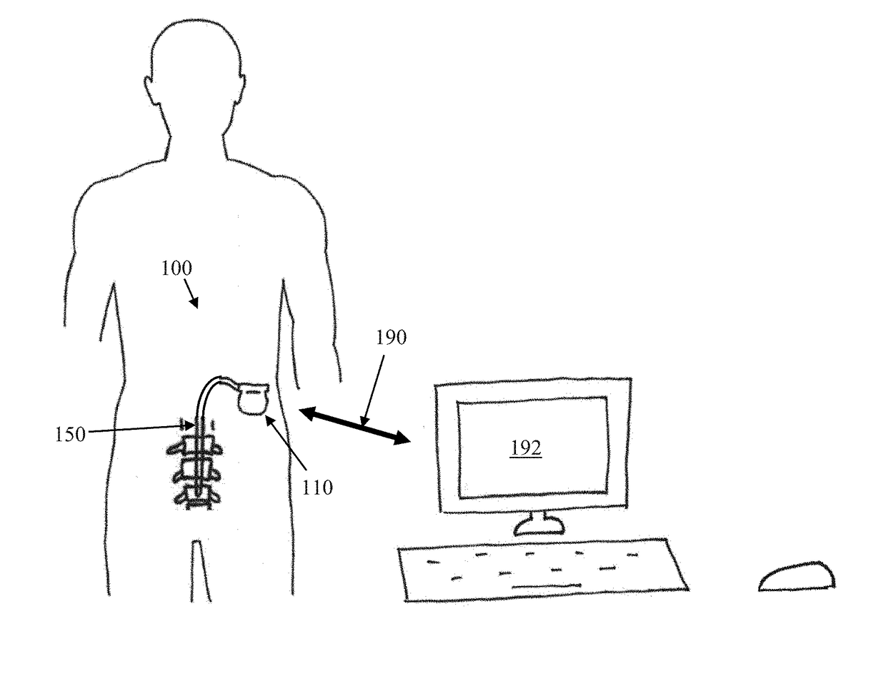
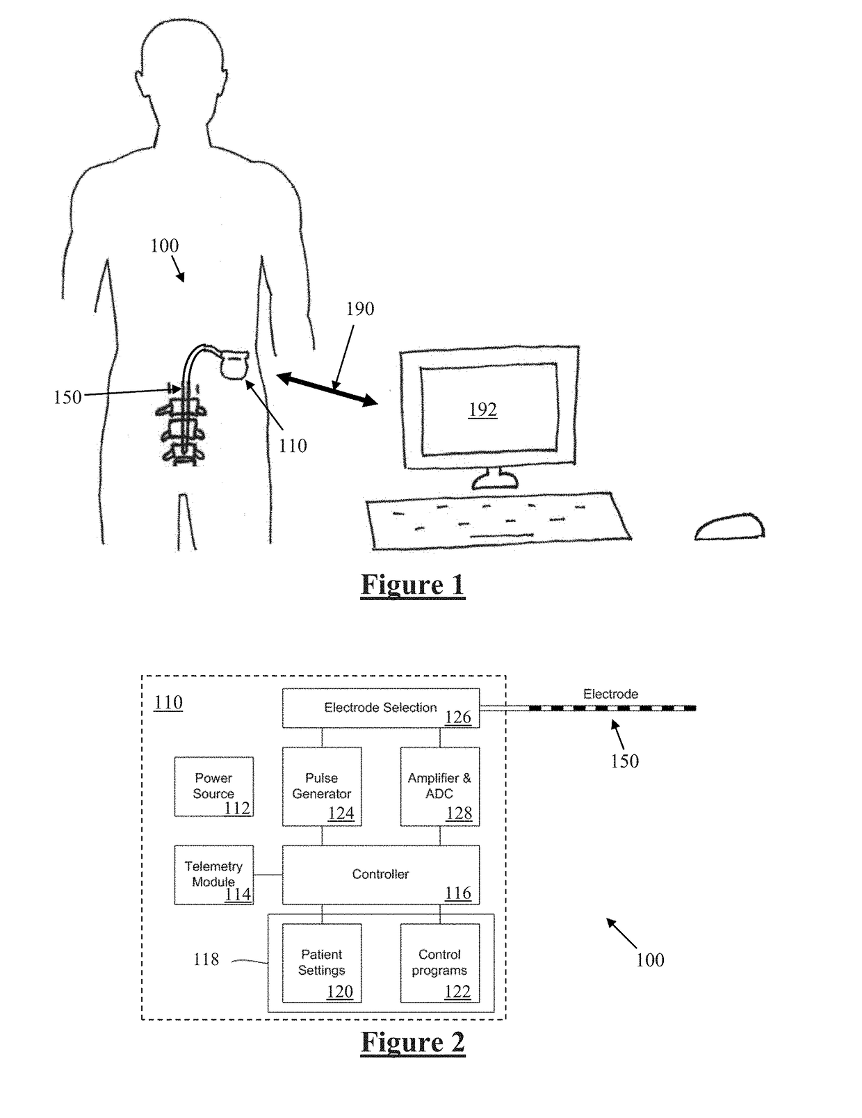
[0039]FIG. 1 schematically illustrates an implanted sacral nerve stimulator 100. Stimulator 100 comprises an electronics module 110 implanted at a suitable location in the patient's lower abdominal area or posterior superior gluteal region, and an electrode assembly 150 implanted within the sacrum and connected to the module 110 by a suitable lead. Numerous aspects of operation of implanted neural device 100 are reconfigurable by an external control device 192. Moreover, implanted neural device 100 serves a data gathering role, with gathered data being communicated to external device 192.

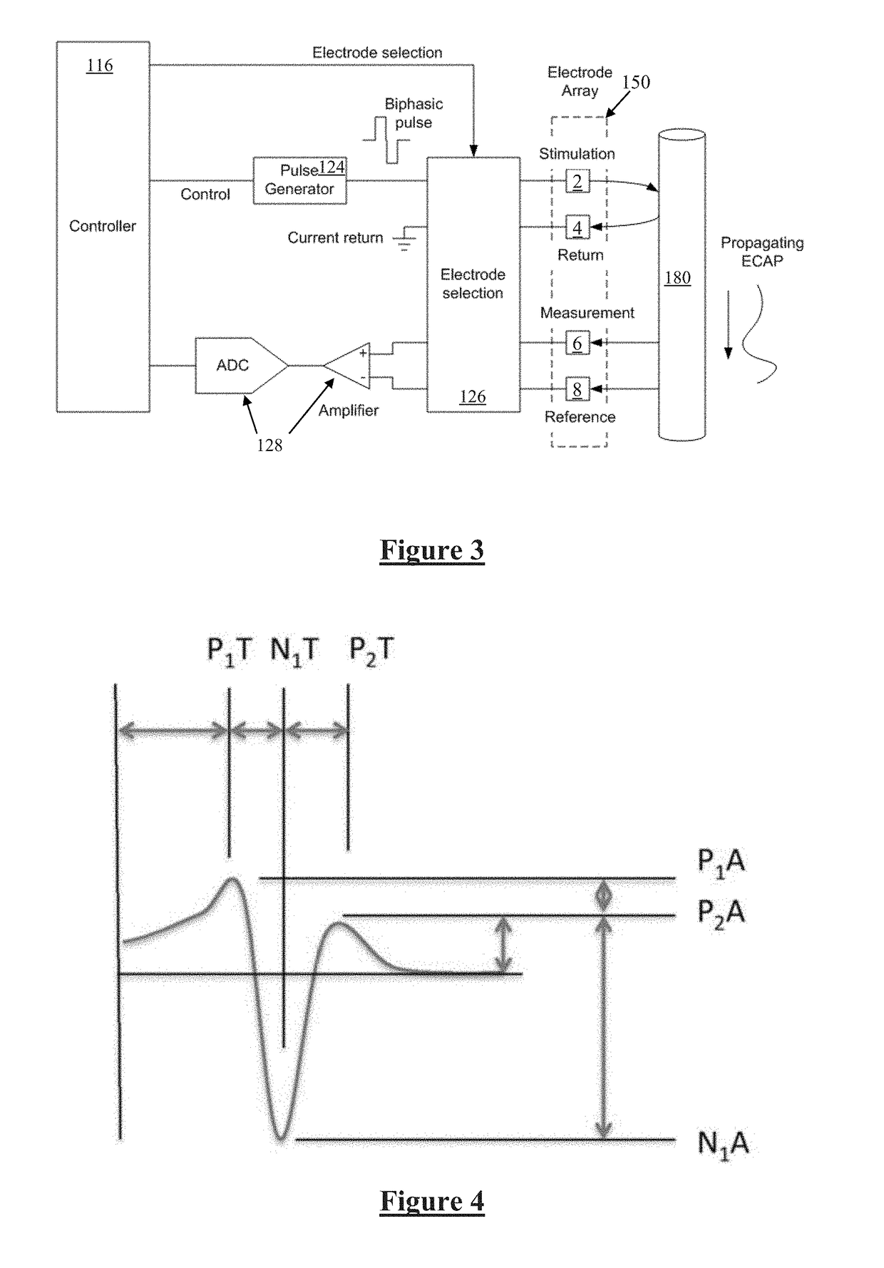
[0040]FIG. 2 is a block diagram of the implanted neurostimulator 100. Module 110 contains a battery 112 and a telemetry module 114. In embodiments of the present invention, any suitable type of transcutaneous communication 190, such as infrared (IR), electromagnetic, capacitive and inductive transfer, may be used by telemetry module 114 to transfer power and / or data between an external device 192 an...


PUM


Abstract

A motor response of a muscle to neural stimulation is assessed. Electrical stimuli are applied from a first electrode to a selected neural pathway to evoke an efferent neural response. A slow neural response upon the neural pathway evoked by the electrical stimuli is observed. Based on the slow neural response, a motor response of at least one muscle to the stimuli is assessed.

Description

CROSS-REFERENCE TO RELATED APPLICATIONS[0001]This application claims the benefit of Australian Provisional Patent Application No. 2015902393 filed 1 Jun. 2015, which is incorporated herein by reference.TECHNICAL FIELD[0002]The present invention relates to neuromodulation delivered to motor fibres, and in particular to a method and device for assessing motor fibre and muscle recruitment from neural response measurements.BACKGROUND OF THE INVENTION[0003]There are a range of situations in which it is desirable to apply neural stimuli in order to give rise to a compound action potential (CAP). A neuromodulation system applies an electrical pulse to tissue in order to generate a therapeutic effect. Such a system typically comprises an implanted electrical pulse generator, and a power source such as a battery that may be rechargeable by transcutaneous inductive transfer. An electrode array is connected to the pulse generator, and is positioned adjacent the target neural pathway(s). An ele...

Claims


Application Information

Patent Timeline
IPC IPC(8): A61B5/11A61B5/04A61B5/00A61N1/36
CPCA61B5/1106A61B5/04001A61B5/4519A61B5/4893A61N1/3605A61B5/4238A61B5/202A61B5/4255A61B5/05A61B5/4052A61B5/4566A61B5/4887A61N1/36057A61B5/4538A61N1/36135A61N1/3615A61B5/24A61N1/00A61N1/205
Inventor PARKER, JOHN LOUIS
Owner CLOSED LOOP MEDICAL PTY LTD
Learn More