
Method for testing a metal detection apparatus and metal detection apparatus

a metal detection apparatus and metal detection technology, applied in the direction of dielectric property measurement, using reradiation, instruments, etc., can solve the problems of single test article, inconvenient testing in detection zones, and inability to measure the sensitivity etc., to achieve the effect of optimizing the performance of the metal detection apparatus

Active Publication Date: 2018-05-17
METTLER TOLEDO SAFELINE
View PDF7 Cites 4 Cited by
  • Summary
  • Abstract
  • Description
  • Claims
  • Application Information

AI Technical Summary

Benefits of technology

The invention provides a method for optimizing metal detection in processed products without extra effort. The method allows for testing the metal detection apparatus with a single test article in different regions of the detection zone, making it possible to verify the presence of required performance and avoid false-positive testing. By using a set of test articles and sensitivity testing, the method can test and optimize the metal detection apparatus for all contaminants that may occur in a product. Additionally, the invention provides predetermined thresholds for efficient execution of tests and reduction of effort.

Problems solved by technology

Hence, for testing and optimising a metal detection apparatus tests with different contaminants need to be performed, which is however time-consuming.
A disadvantage of such a test device is that the sensitivity of the metal detection apparatus is not measured in other regions of the detection zone, which may be more critical than the region, in which the test device is installed.
A single test article, e.g. as delivered by the manufacturer of the metal detection apparatus however is not suitable for performing tests in regions of the detection zone, which exhibit different sensitivities.

Method used


Image

  • Method for testing a metal detection apparatus and metal detection apparatus
  • Method for testing a metal detection apparatus and metal detection apparatus
  • Method for testing a metal detection apparatus and metal detection apparatus

Examples


Embodiment Construction

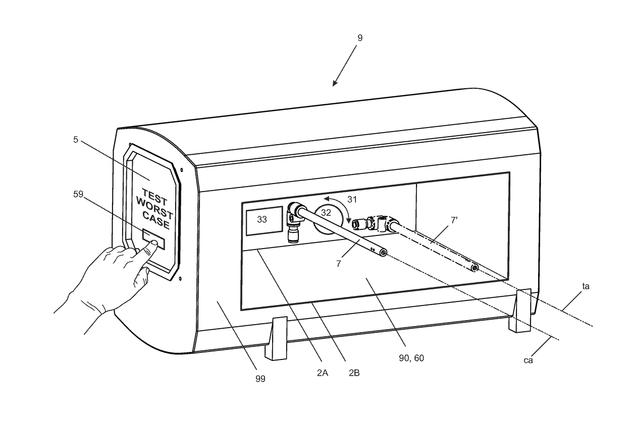
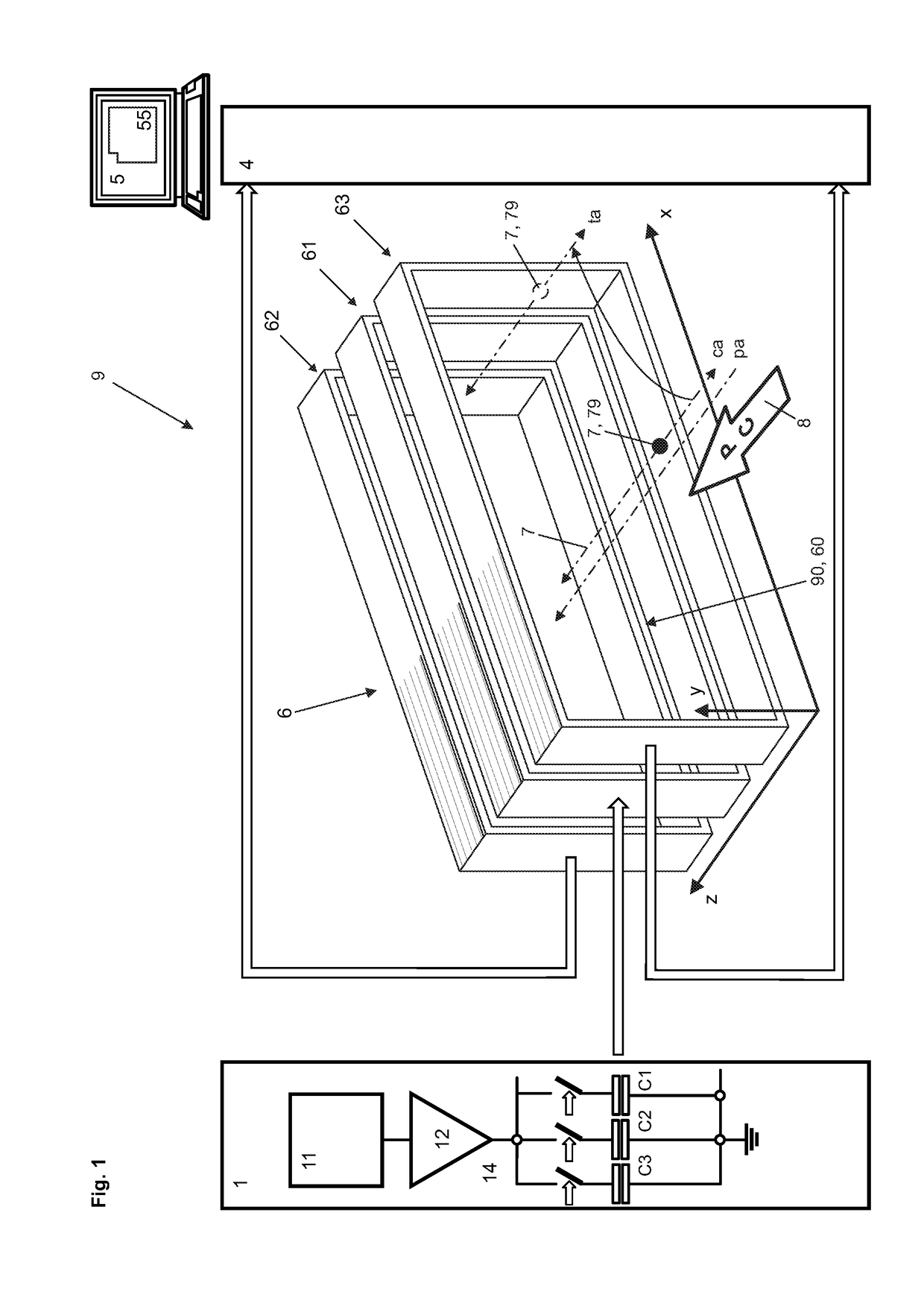
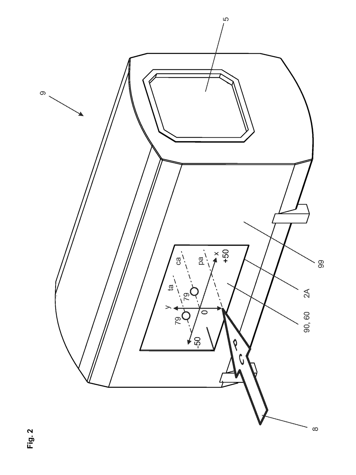
[0064]FIG. 1 schematically shows an inventive metal detection system 9 that comprises a transmitter unit 1, a balanced coil system 6 with a transmitter coil 61, a first and a second receiver coil 62, 63, a receiver unit 4 including a signal processing unit and a control unit 5 such as a standard computer system, that comprises standard interfaces, input devices and output devices, preferably a keyboard and a monitor and in which a program 55 is implemented, with which measurement processes, calibration processes and test processes are controllable. FIG. 1 further symbolically shows a conveyor 8, on which products P, which may comprise metal contaminants C, are transferred along a product axis pa through a transfer channel 90 of the metal detection apparatus 9 (see FIG. 2) and through a detection zone 60 delimited by the balanced coil system 6.

[0065]The transmitter unit 1 comprises a frequency generator 11 that provides a signal with an operating frequency to the input of a power amp...


PUM


Abstract

A metal detection apparatus (9) is tested with a test device (7) having at least one test article (79), movable through a detection zone (60). The test article is moved through the detection zone along a first transfer axis (ca) and a first input signal is measured. A first threshold (th1) is determined, where an amplitude of the first input signal exceeds the first threshold (th1). Then, an identical test article is moved through the detection zone along a further transfer axis (ta; . . . ) and a further input signal is measured and a further threshold (th2; . . . ) is determined, where an amplitude of the further input signal exceeds the further threshold (th2; . . . ). The first or further threshold (th1; th2; . . . ) is selected in the signal processing path (4) whenever the test article is moved along the related transfer axis (ca; ta; . . . ).

Description

CROSS-REFERENCE TO RELATED APPLICATIONS[0001]This application claims priority to European application EP 16198342.4, filed on 11 Nov. 2016, the content of which is incorporated by reference as if fully recited herein.TECHNICAL FIELD[0002]The disclosed embodiments relate to a method for testing a metal detection apparatus and a metal detection apparatus that operates under such a method.BACKGROUND[0003]A metal detection apparatus is used to detect and reject unwanted metal contamination. When properly installed and operated, it will help reducing metal contamination and improving food safety. Most modern metal detectors utilise a search head comprising a “balanced coil system”. Detectors of this design are capable of detecting all metal contaminant types including ferrous, nonferrous and stainless steels in a large variety of products such as fresh and frozen products.[0004]The metal detection apparatus typically comprises a metallic enclosure, having entrance and exit apertures with...

Claims


Application Information

Patent Timeline
IPC IPC(8): G01N27/02G01V3/10G01N27/90
CPCG01N27/023G01V3/107G01N27/9013G01V3/102G01R33/066G01R33/0385G01R27/267G01N27/72G01V13/00G01V3/104
Inventor BUTTERWORTH, DARENBLACKBURN, ANDREW
Owner METTLER TOLEDO SAFELINE
Learn More