Dialysis device and method of dialysis

a dialysis device and dialysis method technology, applied in the field of dialysis devices, can solve the problems of affecting the sterility of the device, and the body losing the ability to adequately remove toxic waste in the blood, so as to improve the sterility of the disposable device, reduce the chance of patient infection, and maintain the effect of the device sterility

a dialysis device and dialysis method technology, applied in the field of dialysis devices, can solve the problems of affecting the sterility of the device, and the body losing the ability to adequately remove toxic waste in the blood, so as to improve the sterility of the disposable device, reduce the chance of patient infection, and maintain the effect of the device sterility

US20180147338A1Active Publication Date: 2018-05-31TEMASEK POLYTECHNIC

Image

  • Dialysis device and method of dialysis
  • Dialysis device and method of dialysis
  • Dialysis device and method of dialysis

Examples


Embodiment Construction

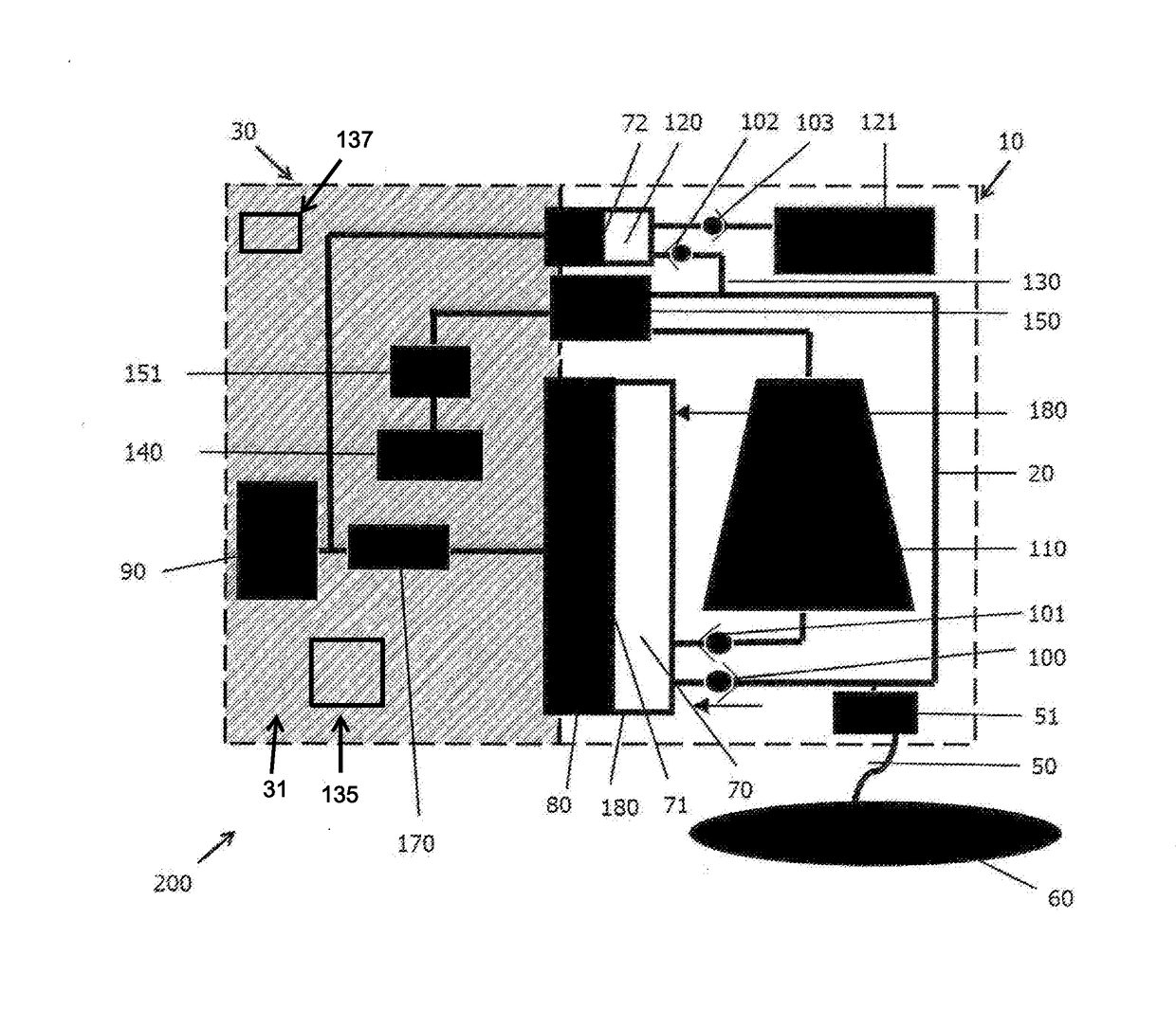
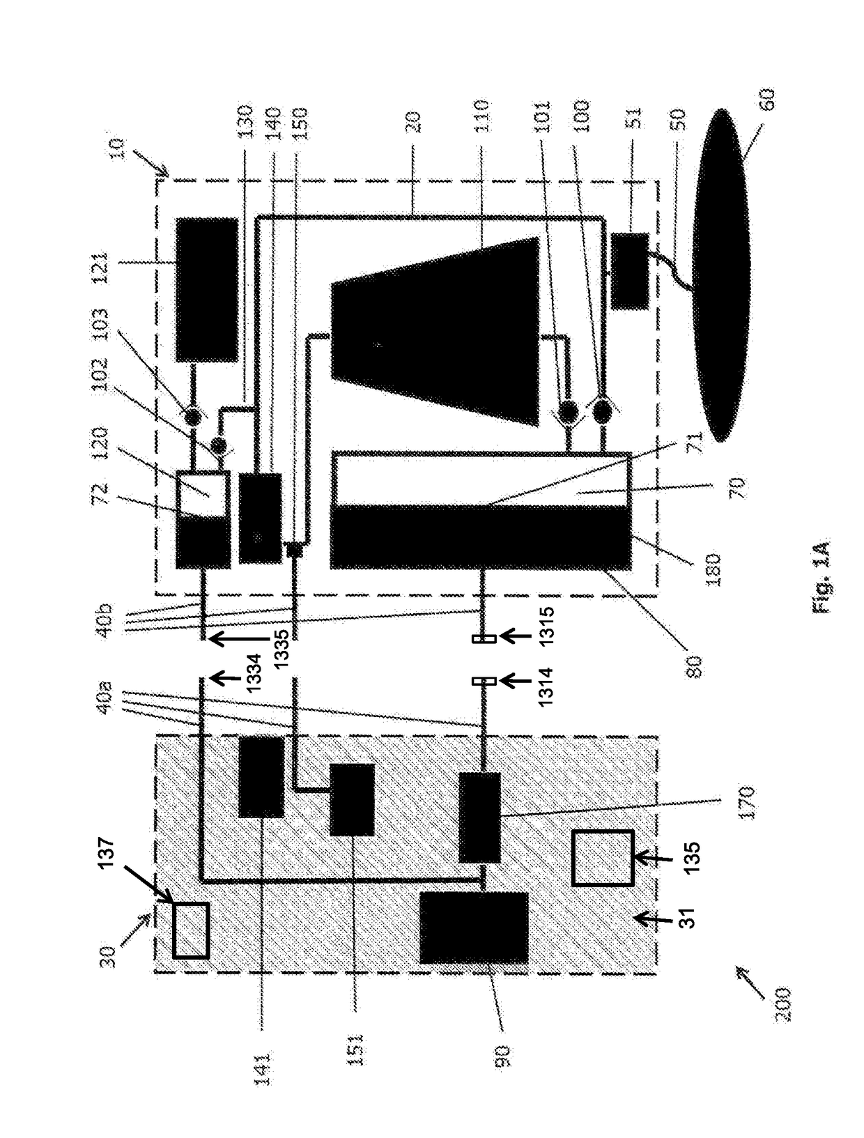
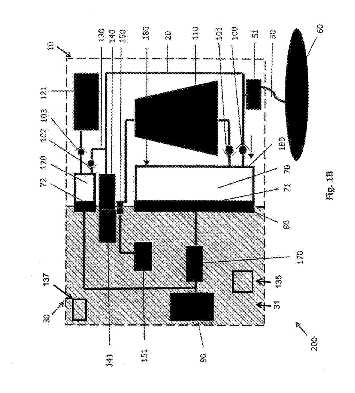
[0056]Exemplary, non-limiting embodiments of a flow system of dialysis device will now be disclosed.

[0057]The flow system of a dialysis device comprises: a disposable housing having a flow path along which dialysate received from a patient is subjected to contaminant removal;

[0058]a controller for controlling the operation of said disposable housing; and

[0059]an interface capable of connecting the controller and the disposable housing to enable contaminant removal from the dialysate;

[0060]wherein the flow path is fluidly sealed from the controller and interface.

[0061]In one embodiment, the disposable housing further comprises a sorbent zone in fluid communication with the dialysate flow path for removing contaminants in the dialysate.

[0062]In one embodiment, the disposable housing further comprises a storage chamber in fluid communication with the dialysate flow path for storing the dialysate therein.

[0063]In one embodiment, the disposable housing further comprises a fluid displacem...


PUM


Abstract

The present disclosure relates to dialysis devices. In some embodiments, a dialysis device may include a disposable housing having a storage chamber in fluid communication with a dialysate flow path. Also included may be a controller, an interface capable of operably coupling the controller and the disposable housing, a fluid displacement structure, a pump configured to actuate a deformable diaphragm, and a pressure sensor to trigger the reversal of the pump. The flow path may be fluidly sealed from the controller and the interface.

Description

TECHNICAL FIELD[0001]The present invention relates to a dialysis device and in particular to a portable or wearable dialysis device. The invention also relates to a method of conducting dialysis.BACKGROUND[0002]Kidneys are vital organs of the human homeostasis system. Kidneys act as a natural filter in the body which remove toxic metabolic wastes such as urea from the blood. Kidney failure or malfunction may lead to an accumulation of toxins and to an imbalanced electrolyte level in the blood, which may result in undesirable repercussions that are hazardous to an individual's health.[0003]Renal dysfunction and / or failure and, in particular, end-stage renal disease, may cause the body to lose the ability to adequately remove toxic waste in the blood and restore the optimal level of electrolytes in the blood, within physiological ranges. Dialysis is commonly used to replace inadequate kidney function by removing toxic waste.[0004]For the past few years, the predominant form of dialysi...

Claims


Application Information

Patent Timeline
31 May 2018
Publication
US20180147338A1
IPC
A61M1/28; A61M1/16
CPC
A61M2209/088; A61M2205/7518; A61M2205/33; A61M2205/128; A61M1/1658; A61M2205/121; A61M1/28; A61M1/1696
Inventors
BLUCHEL, CHRISTIAN GERT; LIN, LIUTONG