
System for determining position of a robot

a robot and position technology, applied in the field of automatic technology, can solve the problems of limiting the application of mobile robots and high cost, and achieve the effects of improving contrast, or signal-to-noise ratio, and improving image contras

Inactive Publication Date: 2018-05-31
ZHU JIXIANG
View PDF9 Cites 11 Cited by
  • Summary
  • Abstract
  • Description
  • Claims
  • Application Information

AI Technical Summary

Benefits of technology

The present invention provides a method for recognizing the position of a mobile robot by comparing a reference image taken previously on a reference route, with a current image taken by the robot. This results in a high stability, simple installation procedure, and low design cost, as compared to prior art robot route-finding methods. The method uses light reflecting tape placed on the ceiling or walls to improve the contrast and signal-to-noise ratio of the position image. The predetermined trajectory of the robot is determined by a number of reference images taken at a perspective of the robot. The method can be used with a remote-controlled robot or a human operator driving the robot along the route to provide the reference images. The method is not influenced by the light when the robot is moved and the installation program is simple. Overall, the method improves the stability and user experience of the mobile robot.

Problems solved by technology

The outgoing goods go through the reverse process, and the routes between the terminal and the various storage shelf are fixed, so it makes sense to automate carriage along these routes However, the current selection of mobile robots requires a complex installation process and the costs are high, which limits the application of mobile robots.

Method used


Image

  • System for determining position of a robot
  • System for determining position of a robot
  • System for determining position of a robot

Examples


Embodiment Construction

[0024]Preferred embodiments of the present invention and their advantages may be understood by referring to FIGS. 1-10b, wherein like reference numerals refer to like elements.

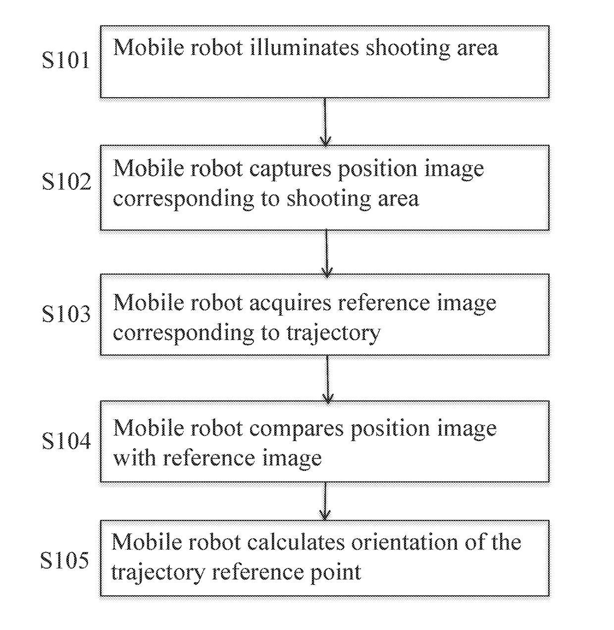
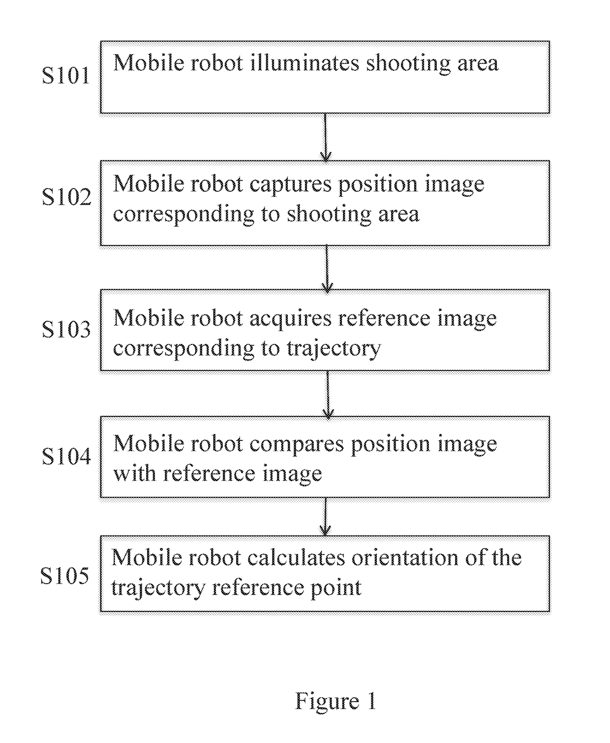
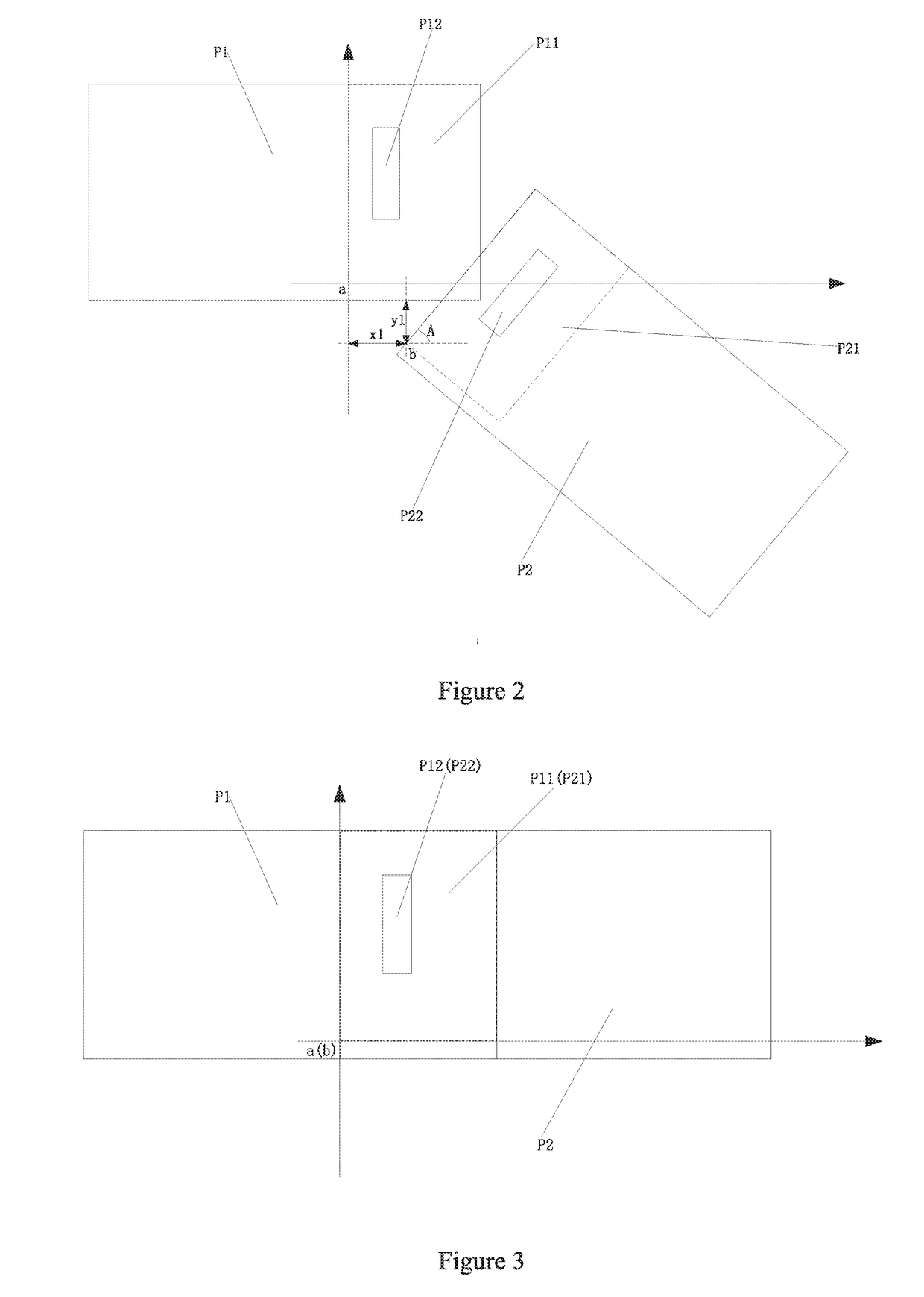
[0025]The present invention describes a method of a robot recognizing its position by comparing one or more images from its current location to one or more reference images showing a view from the ideal path, including i) a mobile robot illuminating a shooting area to be photographed using a monochromatic lighting unit; ii) the mobile robot capturing the position image corresponding to the shooting area through a camera; iii) the mobile robot comparing the position image with one or more reference images corresponding to the trajectory or position of the mobile robot; iv) the mobile robot determining an offset between the position image and the reference image by comparison of the images through identifying overlapping portions of the position and reference images; and v) the mobile robot matching the part of ...


PUM


Abstract

A method for recognizing the position of a mobile robot by comparing images has the steps of a mobile robot illuminating a shooting area to be photographed using a monochromatic lighting unit, the mobile robot photographing the position image corresponding to the shooting area and a narrow band filter passes only the light emitted by the monochromatic lighting unit with the light having same wavelength emitted from the monochromatic lighting unit, reflective or light absorbing material are randomly placed on the shooting area to increase the contrast ratio, and the mobile robot acquiring the reference image corresponding to the trajectory of the mobile robot from the known position image set, wherein the known position image set corresponds to a predetermined trajectory and the known position image set includes a plurality of reference images. A mobile robot may have monochrome lighting for illuminating a shooting area to be photographed.

Description

CROSS-REFERENCE TO RELATED APPLICATION(S)[0001]The present application claims priority to Chinese Patent Application number or patent number 201611078884.8 having a Serial number 2017011900770540 filed on Jan. 23, 2017, entitled“By comparing the position of mobile robot with image recognition and mobile robot.”BACKGROUND OF THE INVENTION1. Field of Invention[0002]The present invention relates to the field of automation technology and, more particularly, to a method for a mobile robot recognizing its position and self-directing by comparing a current image of its position and a previously-taken reference image provided in an earlier process of determining the route.2. Description of Related Art[0003]With the development of science and technology, industrial automation is a growing field of robotic endeavor. In order to reduce labor costs, the mobile robots are used in many factories or warehouses to carry cargo and so on. The mobile robots, such as forklifts or stocking robots, are t...

Claims


Application Information

Patent Timeline
Patent Type & Authority Applications(United States)
IPC IPC(8): G06T7/73G06T7/246G05D1/02
CPCG06T7/74G06T7/248G06T2207/30241G06T2207/10052G05D1/0246G01C21/00G05D1/0244G06T2207/30244G06T2207/30252
Inventor ZHU, JIXIANG
Owner ZHU JIXIANG
Learn More