

Metal alloy composites
a technology of alloys and composites, applied in the field of metal alloy composites and metal alloy composites, can solve the problems of poor mechanical properties of metal alloys such as mg alloys, which are an obstacle to their use in new technologies, and achieve the effect of improving mechanical strength
- Summary
- Abstract
- Description
- Claims
- Application Information
AI Technical Summary
Benefits of technology
Problems solved by technology
Method used
Image

Examples
example 1
Materials
[0263]The Mg-alloy used for this example was AZ31 with ˜3.0 at % aluminum—available commercially (Taiwan Mach Technology (LINYI) Co.). The chemical composition of the alloy cited by the manufacturer is presented in Table 11.
TABLE 11Chemical composition (in wt %) of theAZ31 alloy (Mg is about 94.5 wt %).ElementsAlZnMnSiFeCuNiMgwt %3.080.9080.3930.0220.0010.0020.01Balance
[0264]The WS2 nanotubes were produced by the reaction of slightly reduced WO3 nanoparticles with H2S at temperatures between 850-900° C. using a fluidized bed reactor, (i.e. a vertical reactor where the reacting powder is fluidized (levitated) by a streaming upwards of gas, such as nitrogen, in addition to the reactive gasses, i.e. H2S and H2).
example 2
Preparation of Mg MMC Comprising Inorganic Nanotube
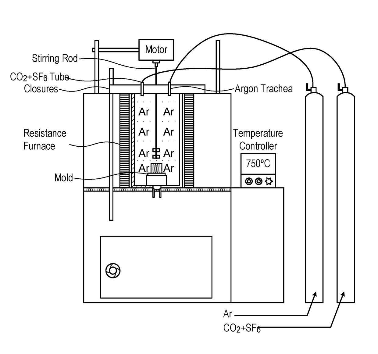
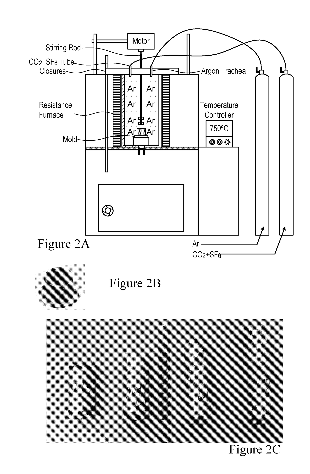
[0265]The AZ31 and the WS2 nanotubes were placed inside a graphite crucible and heated to 400° C. in a resistance-heating furnace for 15 minutes; then a stirring vane was applied; meanwhile, CO2 and SF6 gasses were bubbled into the crucible to help mixing the melt. The CO2 and the SF6 gasses were also helpful in preventing oxidation of the melt by residual water and air. After that, the melt was heated up to 600° C. for 15 minutes. The crucible was further heated gradually up to 700-720° C., with the molten alloy being stirred with a vane operated at 350 rev / min for 3 minutes. Finally, the composite melt was poured into a metallic mold. The Mg MMCs containing nanotubes with weight fraction of 0.1-1 wt % (see Table 12) were now ready for further mechanical testing. Each composition was repeated at least three times. Initially, blade stifling (“a” in Table 12) was used for mixing the nanotubes in the metal melt. However, due to the sm...
example 3
Analysis of Mg MMC Comprising Inorganic Nanotube
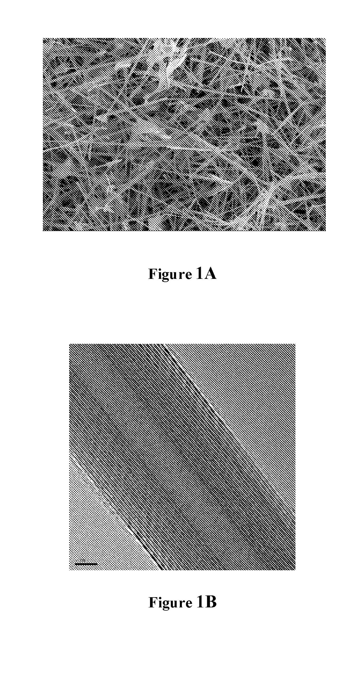
[0267]A vertical theta-theta diffractometer (TTRAX III, Rigaku, Japan) equipped with a rotating Cu anode operating at 50 kV and 240 mA was used for XRD studies. The following electron microscopes were used in this work: SEM model LEO model Supra, 7426. The SEM was equipped with EDS system model Oxford INCA. TEM (Philips CM120 TEM) operating at 120 kV was equipped with an EDS detector (EDAX-Phoenix Microanalyzer). For electron microscopy and analysis, the collected powder was sonicated in ethanol and placed on a carbon-coated Cu grid (for TEM).
[0268]For the mechanical testing, an MTS Model 458 axial / torsional testing systems was used according to standard ASTM B 557M-02a (Standard Test Methods of Tension Testing Wrought and Cast Aluminum- and Magnesium-Alloy Products).
[0269]For analysis, samples (5×5×3 mm3) were cut from the top, middle and bottom of the ingot. Minute oxidation of the top and bottom surfaces was unavoidable, but was lim...
PUM
| Property | Measurement | Unit |
|---|---|---|
| Temperature | aaaaa | aaaaa |
| Temperature | aaaaa | aaaaa |
| Temperature | aaaaa | aaaaa |
Abstract
Description
Claims
Application Information