
Method for making a semiconductor device with nanowire and aligned external and internal spacers

a technology of external and internal spacers and semiconductors, applied in the field of making a semiconductor device with a nanowire or a nanowire, can solve the problems of increasing the interference capacitance within the transistor, unable to achieve a high nanowire density, and unable to achieve the desired positioning and gate pattern. satisfactory and satisfactory definition of the gate pattern are difficult to achieve,

Active Publication Date: 2018-06-21
COMMISSARIAT A LENERGIE ATOMIQUE ET AUX ENERGIES ALTERNATIVES
View PDF0 Cites 13 Cited by
  • Summary
  • Abstract
  • Description
  • Claims
  • Application Information

AI Technical Summary

Benefits of technology

The patent text proposes a method for making semiconductor devices more efficiently. The method involves releasing a nanowire beforehand and then depositing a sacrificial material that can be selectively etched relative to the nanowire. This allows for better control over the etching process and results in an internal spacer that is correctly aligned with an external spacer. The external spacer is made of a dielectric material with a low dielectric permittivity, which reduces interference capacitances and improves the operating speed of CMOS circuits. Additionally, the method includes making isolation trenches around the nanowire to facilitate a high nanowire density.

Problems solved by technology

As a result of these design rules, the overall dimensions of the semiconductor blocks forming the source and the drain are large and do not allow a high nanowire density to be achieved.
Furthermore, satisfactory positioning as well as satisfactory definition of the gate pattern prove to be difficult to achieve.
The drawback of such an approach is that the etching used to remove the SiGe at the channel region does not stop at the level of the opening formed in the mask layer for removal of the sacrificial gate, with this etching spreading towards the source and drain regions.
This results in an increase in interference capacitances within the transistor, since during the filling of the cavity with gate material some zones at the edge of the gate cover the source and drain zones.

Method used


Image

  • Method for making a semiconductor device with nanowire and aligned external and internal spacers
  • Method for making a semiconductor device with nanowire and aligned external and internal spacers
  • Method for making a semiconductor device with nanowire and aligned external and internal spacers

Examples


Embodiment Construction

[0011]Thus there is a need to propose a method for making a semiconductor device with semiconductor nanowire or nanowires which allows correct alignment of the internal spacer in relation to, or regarding, the external spacer to be achieved, which is suitable for making transistors with a high density on the support and which does not possess the above-mentioned drawbacks of the methods of the prior art.

[0012]In order to achieve this, one embodiment proposes a method for making at least one semiconductor device which comprises at least:

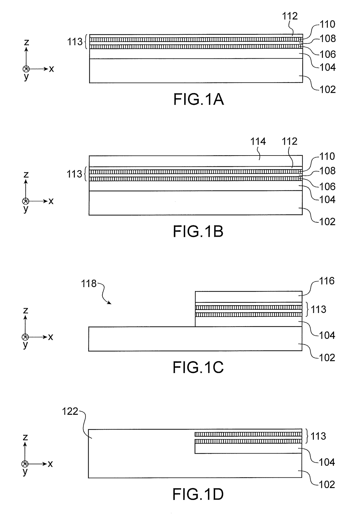
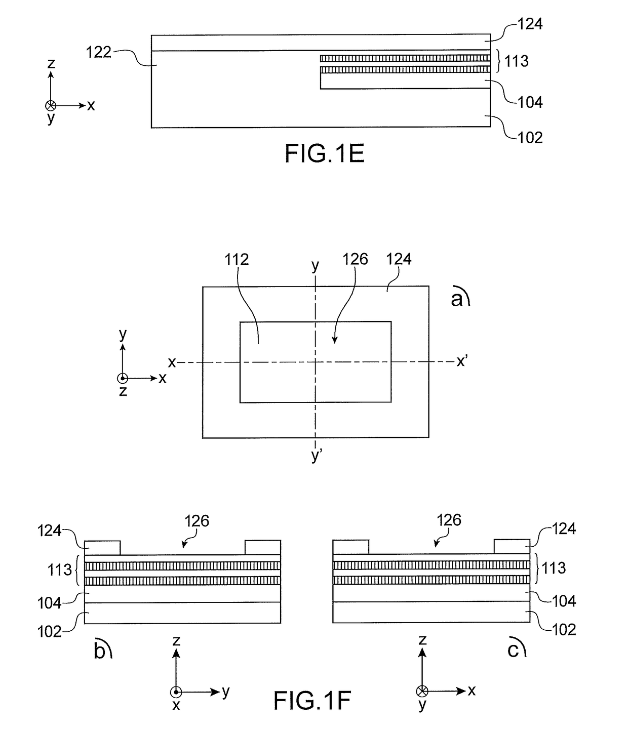
[0013]a) making, on a support, of a stack of layers comprising at least one first crystalline semiconductor layer and at least one second crystalline semiconductor layer capable of being selectively etched in relation to, or regarding, the semiconductor of the first layer, wherein the second layer is arranged between the first layer and the support;

[0014]b) etching of part of the stack of layers such that at least one portion of the first layer forms ...


PUM


Abstract

Method for making a semiconductor device, comprising:a) making of a stack of crystalline semiconductor layers comprising a first layer and a second layer capable of being selectively etched in relation to the first layer,b) etching of part of the stack, a portion of the first layer forms a nanowire (132) arranged on the second layer,c) selective etching of second layer,d) making, beneath the nanowire, of a sacrificial portion which has an etching selectivity which is greater than that of the second layer,e) making of a sacrificial gate and of an external spacer surrounding the sacrificial gate,f) etching of the stack, revealing ends of the nanowire and of the sacrificial portion aligned with the external spacer,g) selective etching of parts of the sacrificial portion, from its ends, forming aligned cavities beneath the external spacer,h) making of an internal spacer within the cavities.

Description

TECHNICAL FIELD AND PRIOR ART[0001]This document concerns a method for making a semiconductor device with semiconductor nanowire or nanowires and comprising an internal spacer which is aligned relative to an external spacer. This document applies in particular to the making of transistors with multiple gates, or multi-gate transistors, for example of the GAAFET (Gate-All-Around Field-Effect Transistor”) type. This document applies in particular to the field of FET devices used for high-performance, low energy-consumption logic applications in microelectronics, as well as that of the design and manufacture of FET transistors which each comprise several nanowires superimposed upon each other, used in the design of integrated circuits which have improved electrical performance levels in comparison with the state of the art.[0002]This document advantageously applies to the making of one or more GAAFET transistors which are co-integrated, on the same substrate, with one or more FinFET (“...

Claims


Application Information

Patent Timeline
IPC IPC(8): H01L29/66H01L29/423H01L29/78H01L29/06
CPCH01L29/6681H01L29/6653H01L29/6656H01L29/66553H01L29/66545H01L29/42392H01L29/7853H01L29/0673H01L29/78696H01L29/78654H01L29/78684H01L27/1211H01L29/775B82Y10/00H01L29/66439H01L29/1079
Inventor BARRAUD, SYLVAINAUGENDRE, EMMANUELCOQUAND, REMIREBOH, SHAY
Owner COMMISSARIAT A LENERGIE ATOMIQUE ET AUX ENERGIES ALTERNATIVES
Learn More