
Card reader

a card reader and card reader technology, applied in the field of card readers, can solve the problems of so-called skimming, and achieve the effect of reducing the risk of accidental damag

Inactive Publication Date: 2018-07-12
SANKYO SEIKI MFG CO LTD
View PDF3 Cites 2 Cited by
  • Summary
  • Abstract
  • Description
  • Claims
  • Application Information

AI Technical Summary

Benefits of technology

The present invention is about a card reader that prevents a drop in the total inductance of its coil, even when there is not enough space for the coil near the card insertion port and magnetic stripe position. This is achieved by using a special design that maintains the magnetic field generated by the coil, even in areas where it may be affected by external factors.

Problems solved by technology

In an industry of financial institutions and the like where the card reader is utilized, conventionally, a so-called skimming has become a serious problem in which a criminal attaches a magnetic head to a card insertion part of the card reader to illegally acquire magnetic data of a card by using the magnetic head.

Method used


Image

  • Card reader
  • Card reader
  • Card reader

Examples


Embodiment Construction

[0022]Embodiments of the present invention will be described below with reference to the accompanying drawings.

(Structure of Card Reader)

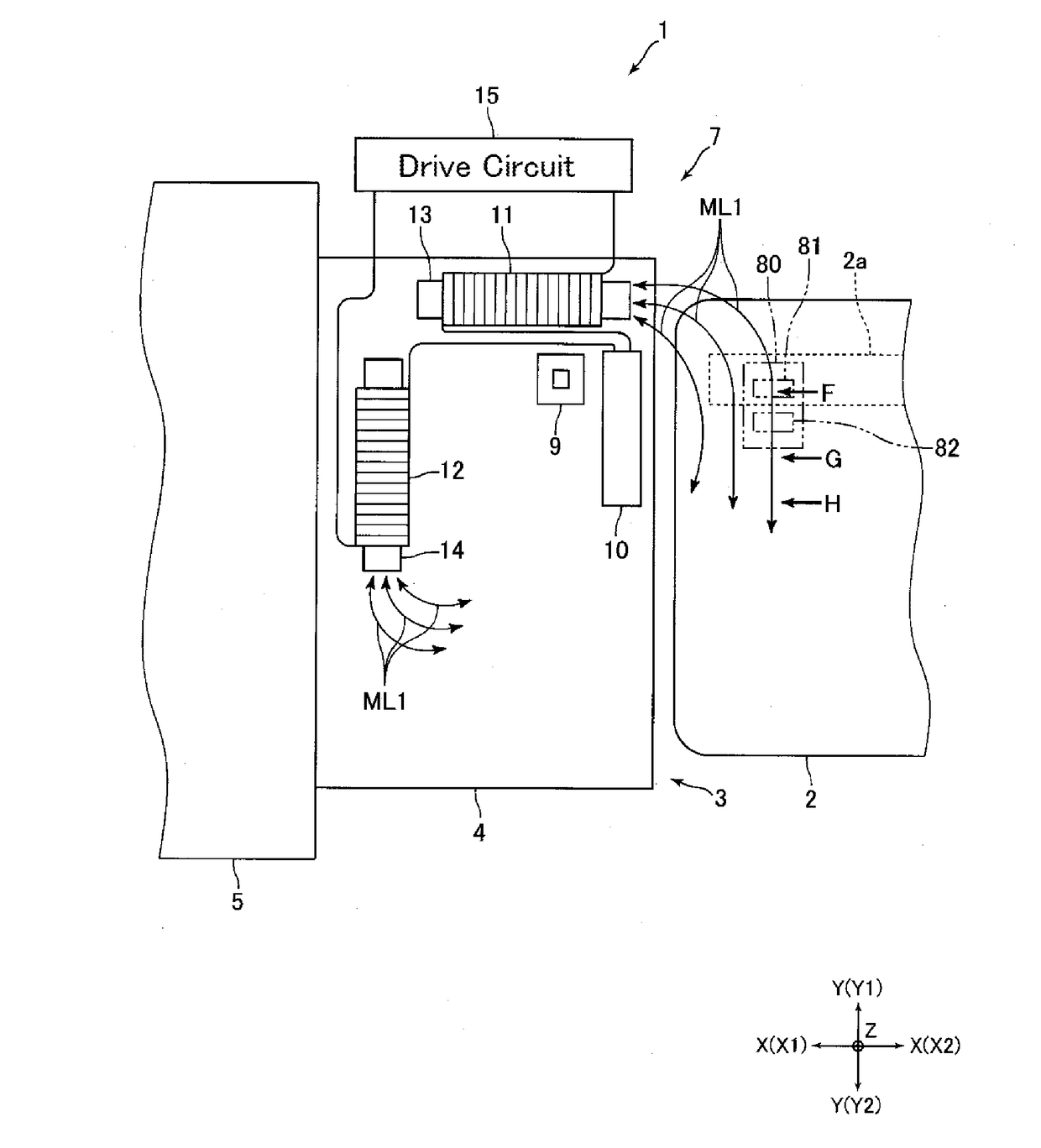
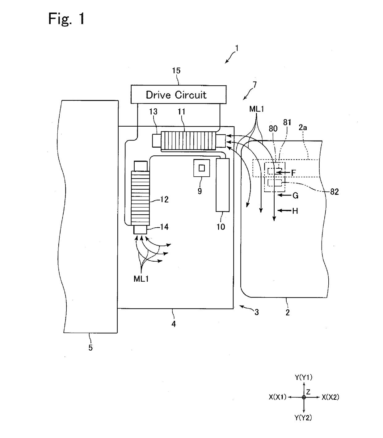
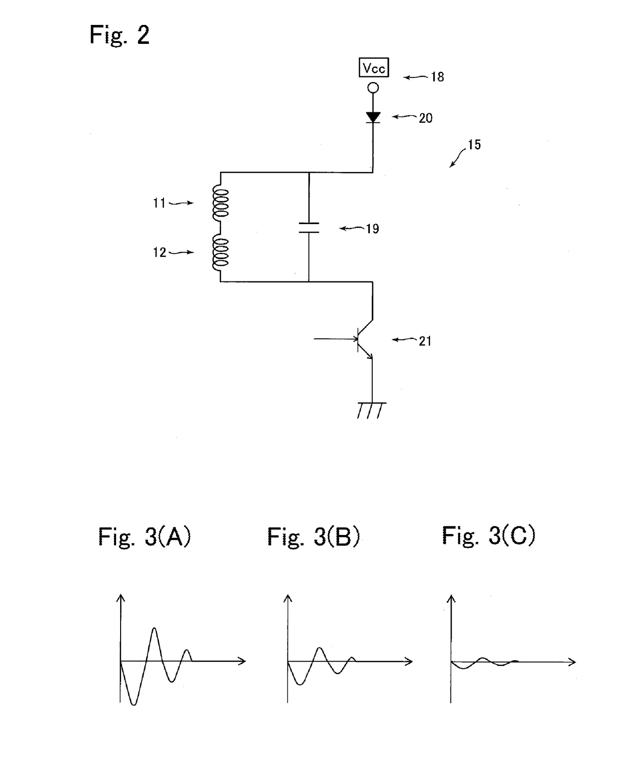
[0023]FIG. 1 is an explanatory schematic plan view showing a structure of a front end side portion of a card reader 1 in accordance with an embodiment of the present invention. FIG. 2 is a schematic circuit diagram showing a drive circuit 15 structured to supply a current to coils 11 and 12 shown in FIG. 1. FIGS. 3(A), 3(B) and 3(C) are views for explaining intensity of a disturbing magnetic field generated by a disturbing magnetic field generation means 7 shown in FIG. 1.

[0024]A card reader 1 in this embodiment is a device which is structured to perform reading of magnetic data recorded on a card 2 and / or recording of magnetic data on a card 2, and is, for example, mounted and used in a host apparatus such as an ATM. The card reader 1 includes a card insertion part 4 in which a card insertion port 3 into which a card 2 is inserted is formed, and a...


PUM

PropertyMeasurementUnit
magneticaaaaaaaaaa
magnetic fieldaaaaaaaaaa
electric currentaaaaaaaaaa

Abstract

A card reader for use with a card having a magnetic stripe may include a card insertion port into which the card is inserted; a card passage along which the card is passed; and a disturbing magnetic field generation means structured to generate a magnetic field for disturbing illegal reading of magnetic data recorded in the magnetic stripe. The disturbing magnetic field generation means may include a plurality of coils which are serially-connected with each other; a capacitor connected in parallel with the plurality of the coils; and a drive circuit structured to supply an electric current to the plurality of the coils.

Description

TECHNICAL FIELD[0001]The present invention relates to a card reader structured to perform reading of magnetic data recorded on a card and / or recording magnetic data to a card.BACKGROUND ART[0002]Conventionally, a card reader structured to read magnetic data recorded on a card and / or to record magnetic data on a card has been widely utilized. In an industry of financial institutions and the like where the card reader is utilized, conventionally, a so-called skimming has become a serious problem in which a criminal attaches a magnetic head to a card insertion part of the card reader to illegally acquire magnetic data of a card by using the magnetic head. Therefore, a card reader has been proposed which is structured to generate a disturbing magnetic field for preventing reading of magnetic data by a magnetic head for skimming (hereinafter, referred to as a “skimming magnetic head”) (see, for example, Patent Literature 1).[0003]The card reader described in Patent Literature 1 includes ...

Claims


Application Information

Patent Timeline
Patent Type & Authority Applications(United States)
IPC IPC(8): G06K7/08G11B5/008G07F7/08
CPCG06K7/084G11B5/00808G07F7/0873G06K7/08G07D9/00G07F19/2055
Inventor SAKAMAKI, HIROTAKA
Owner SANKYO SEIKI MFG CO LTD
Learn More