Filter Arrangement

a filter arrangement and filter technology, applied in the direction of power conversion systems, electrical equipment, coupling device connections, etc., can solve the problems of high currents that must be transmitted on the busbar between the energy storage, the electric motor, and the time-consuming and cost-intensive, and achieve the effects of improving filter characteristics, low transition resistance, and reducing production costs of the filter arrangemen

Active Publication Date: 2018-07-12
INTICA SYST AG
View PDF6 Cites 8 Cited by
  • Summary
  • Abstract
  • Description
  • Claims
  • Application Information

AI Technical Summary

Benefits of technology

[0007]The filter arrangement according to the invention offers the key advantage that the electrical connection between busbar and filter component can be produced simply and at a favorable cost through the mechanical mounting. Thereby, in particular, a welding of the connection regions of the filter components on the busbars can be avoided. This leads, on the one hand, to a reduction of contacting faults, and on the other hand to cost advantages in the production of the filter arrangement.
[0011]In a preferred example embodiment, the carrier element protrudes laterally on both sides of the busbars and on the protruding regions respectively a filter component, in particular an electrical capacitor, is provided. The protruding regions serve thereby as connection regions for the filter components. Thereby, the electrical lines between busbar and filter component can be kept short.
[0015]In a preferred example embodiment, the electrical connection between the busbar and a conducting region arranged on the carrier element is achieved via a contact section (contact spring) having at least one contact region configured in a spring-like manner. This contact region configured in a spring-like manner can be at least partially elastically deformed or respectively compressed when clamping the carrier element between the busbars. Thereby, an improved electrical contacting of the busbars can be achieved.
[0020]In a preferred example embodiment, the carrier element has a carrier of an electrically non-conducting material, and punched sheet metal parts arranged thereon. The punched sheet metal parts serve here for the respective electrical contacting of the filter component toward the busbar and toward the component lying at reference potential. Thereby, the production costs of the filter arrangement can be further reduced.
[0021]In a preferred example embodiment, the contact region, configured in a spring-like manner, is provided in one piece on a punched sheet metal part connecting the busbar to the filter component. In other words, the contact region, configured in a spring-like manner, forms an integral part of a punched sheet metal part situated for contacting between busbar and filter component. Thereby, a soldering of a contact element to the punched sheet metal part can be avoided, which leads to low transition resistances and thereby to improved filter characteristics.
[0022]In a preferred example embodiment, the filter arrangement comprises a plurality of carrier elements, the carrier elements being spaced from one another along the busbars, each carrier element comprising at least one filter component. Between these carrier elements a choke can be provided, which is formed by a ring-shaped magnet core or respectively by a wound strip core, in particular a nanocrystalline strip core. The choke can have in particular an inner opening which is adapted to the cross-section of the busbars, clamped against one another, such that the choke is able to be slid onto the busbars. Through the inductive effect of the magnet core on the busbar, the effect of a choke is achieved.

Problems solved by technology

In particular in electrically driven vehicles, the problem exists that high electric currents must be transmitted on busbars between the energy storage (e.g. battery unit) and the electric motor (e.g. currents up to 500 A).
This is, on the one hand, time-consuming and cost-intensive, but on the other hand error-prone, because the quality of the electrical contact depends significantly on the quality of the welded connection, which is subject to considerable variations.

Method used


Image

  • Filter Arrangement
  • Filter Arrangement
  • Filter Arrangement

Examples


Embodiment Construction

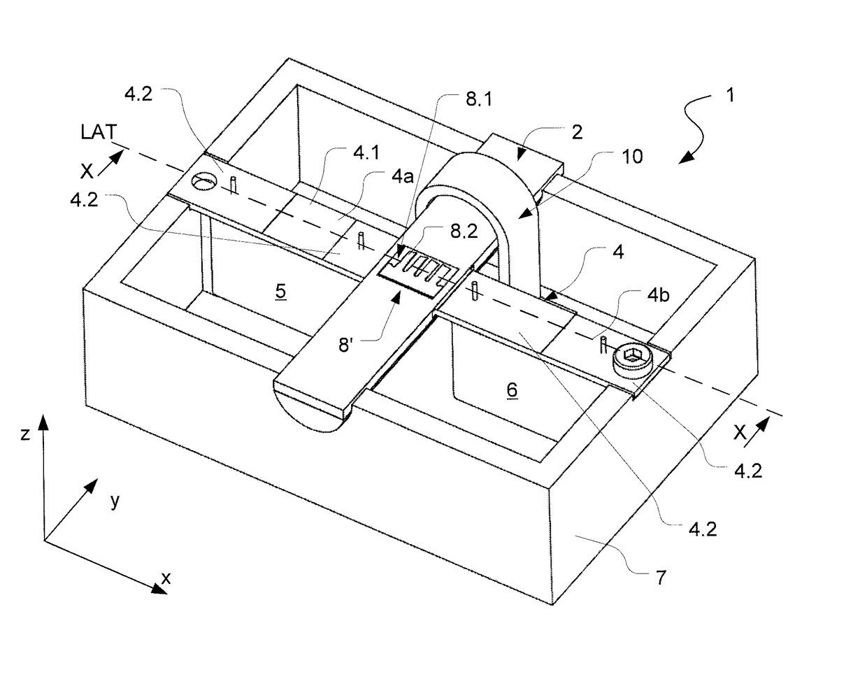
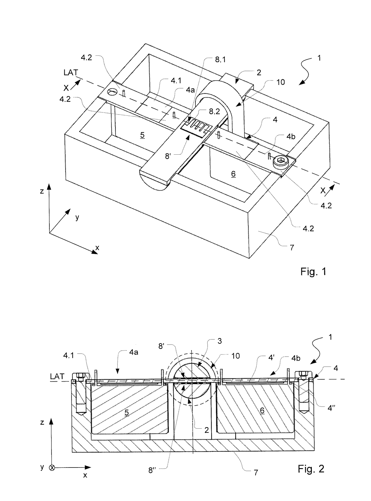
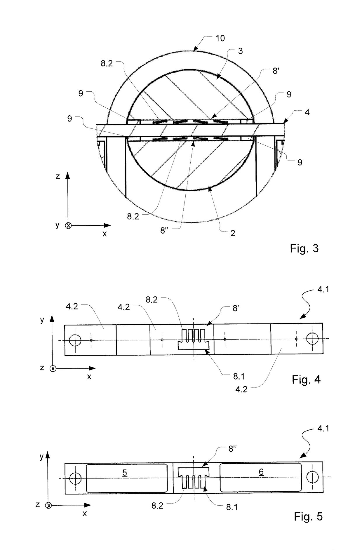
[0039]FIGS. 1 to 5 show a first example embodiment of a filter arrangement 1 in different views. The following description of the filter arrangement 1 is made with reference to a Cartesian coordinate system with axes standing perpendicularly to one another, namely an x-axis, a y-axis and a z-axis. The filter arrangement 1 comprises a busbar pair with a first busbar 2 and a second busbar 3. In the illustration according to FIG. 1, only the first busbar 2 is shown. It shall be understood that more than two busbars can be provided for the formation of the filter arrangement 1.

[0040]The busbars 2, 3 of the filter arrangement 1 build, for example, a positive and a negative electrical conductor, which connects an energy storage unit, for example an electrical battery, to an electrical consumer, for example an electric motor. In the shown example embodiment, the busbars 2, 3 are arranged one above the other in z-direction and run with their longitudinal axes (LAS) parallel to one another i...


PUM


Abstract

The invention relates to a filter arrangement having a first busbar, a second busbar and a carrier element, on which at least one electrical filter component is arranged, which is electrically connected to the busbars, wherein the electrical connection of the at least one electrical filter component to at least one of these busbars is realized by mechanical clamping of the carrier element between the first and second busbar.

Description

BACKGROUND OF THE INVENTION[0001]The invention relates to a filter arrangement and a method for producing a filter arrangement.[0002]Electric or electronic filters for interference suppression of electrical systems and installations are basically known. In particular, filters are known which in a direct current network filter out high-frequency signals which are coupled into direct current paths, in order to meet the existing requirements with regard to electromagnetic compatibility (EMC) of the electrical system or of the installation (so-called EMC filters).[0003]In particular in electrically driven vehicles, the problem exists that high electric currents must be transmitted on busbars between the energy storage (e.g. battery unit) and the electric motor (e.g. currents up to 500 A). Therefore, the busbars must have a considerable cross-section (e.g. in the cm2 range) in order to prevent an excessive heating of the busbars. Electrical components, in particular capacitors, must be c...

Claims


Application Information

Patent Timeline
Patent Type & Authority Applications(United States)
IPC IPC(8): H02B1/20H03H1/00
CPCH02B1/20H03H1/0007H03H1/00H03H2001/0021H01R13/2492H02M1/44H02M7/003
Inventor WURZINGER, MATHIAS
Owner INTICA SYST AG
Why Eureka
Try Eureka