

Gantry cutting machine for pipe and flat plate
- Summary
- Abstract
- Description
- Claims
- Application Information
AI Technical Summary
Benefits of technology
Problems solved by technology
Method used
Image

Examples
embodiment
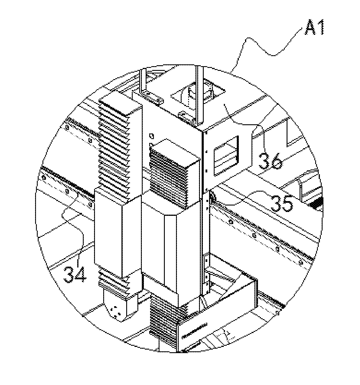
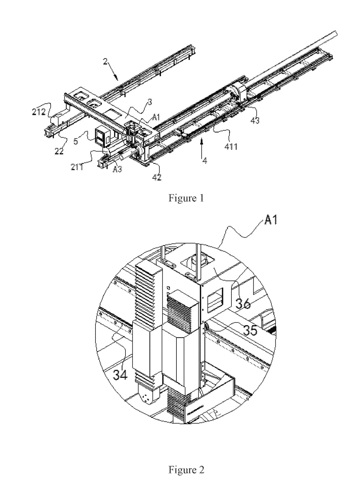
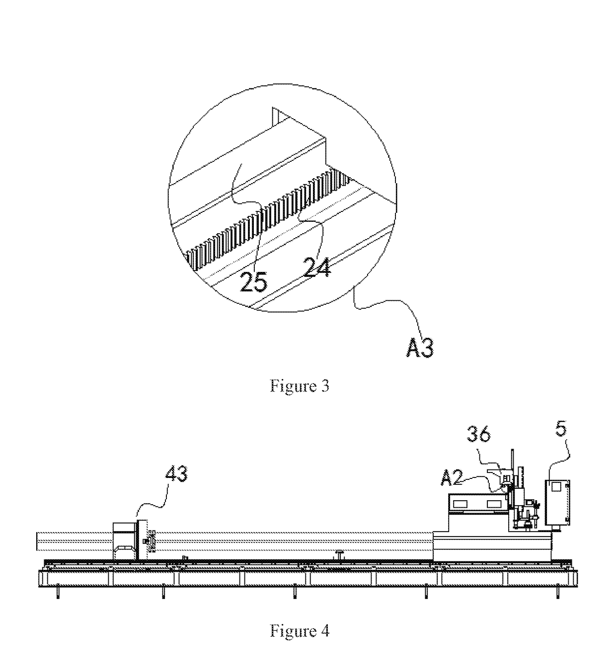
[0097]As shown in FIG. 1 to FIG. 25, a gantry cutting machine for pipe and flat plate includes at least one cutting assembly, plate cutting mechanism 2, pipe cutting mechanism 4 for cutting rectangular pipes and crossbeam 3. The plate cutting mechanism and the pipe cutting mechanism are arranged side by side, the crossbeam is located above the plate cutting mechanism and the pipe cutting mechanism, and the end provided with a cutting torch is defined as front end.
[0098]The crossbeam is provided with a transverse driving unit for driving the cutting assembly to move along a length direction of the crossbeam, the cutting assembly is connected to the crossbeam through cutting assembly mounting base 36, and the cutting assembly mounting base is provided with a lifting-driving unit for driving the cutting assembly to move up and down.
[0099]The transverse driving unit includes first gear 31, first rack 32, first motor, and first rail 34. The first gear and the first rack are engaged with ...
PUM
| Property | Measurement | Unit |
|---|---|---|
| Angle | aaaaa | aaaaa |
| Angle | aaaaa | aaaaa |
Abstract
Description
Claims
Application Information