Air purifier

a technology of air purifier and air filter, which is applied in the field of air purification, can solve the problems of ionized particles escaping into the air, affecting lung function, and t filtering very small, and achieve the effect of reducing flow turbulen

Active Publication Date: 2018-07-19
QINGDAO RANDALL AERODYNAMICS ENG LLC
View PDF0 Cites 10 Cited by
  • Summary
  • Abstract
  • Description
  • Claims
  • Application Information

AI Technical Summary

Benefits of technology

[0011]The present invention is directed to an air purifier system. A simple embodiment of the air purifier, as depicted in FIG. 1, has a flow path from back-to-front. Air flows through the docking ring (4) and then through either a prefilter (9) and / or a barrier. A barrier could be any arrangement of material that protects the fan blades from foreign objects and / or people's fingers from the fan blades. A prefilter (9) could provide similar protection while removing large dust particles from the flow and reducing flow turbulence.
[0012]The fan (6) is surrounded by a housing (15) that improves fan (6) effectiveness near its blade tips. This is done by reducing tip vortices, which are caused by flow acceleration from the high-pressure side (downstream) of the blades to their low-pressure side (upstream) around blade tips. The fan (6) is driven by a motor (13). It represents the aerodynamic heart of the air purifier system, providing energy to the flow and pushing air downstream. Custom fan (6) design is critical to overall system performance. The flow must approach blades tangent to their leading edges (28), flow over blades without separation, and leave tangent to the blade's trailing edges (29).
[0013]A filter (16) can remove virtually all of the dust from the air, including tiny particles smaller than 2.5 microns in characteristic diameter. Outgoing air is clean and healthy, and the energy consumed by the motor (13) is reasonably low.
[0015]The inlet (7) allows flow to smoothly enter the housing without separation, which would cause “vena contracta” and reduce the fan's (6) efficiency near its blade tips. (31). The hub dome (34) allows flow to remain attached as it approaches blade roots (30) to improve fan (6) efficiency in that region. The motor cover (14) allows the flow to travel smoothly over the motor without separation.
[0018]The air purifier system provides a technical solution for ventilation and purification, which is achieved by placing the air purifier system on a windowsill or stand (40) and using the height and level adjusters (11) to align the docking ring (4) with an air inlet hole (35), as seen in FIG. 13. Turning on the air purifier drives ventilation air through a filter before allowing it to exhaust into a space. The inside space becomes slightly pressurized, which forces stale air out through leaks. In so doing, little or no dirty air leaks-in and diffuses throughout a space, so only a small amount of air must be forced through the filter. This technique requires approximately one-eighth the amount of energy required to provide ventilation and clean air by slightly opening windows and using a standalone in-room filter. The air purifier system is not expensive to produce and can be used in rented and leased spaces. Installation can be achieved by cutting an air inlet hole (35) in a window, or by replacing an existing window screen with a transparent plastic sheet having an air inlet hole (35) cut into it.
[0025]Compared with the prior art, the air purifier system is: energy efficient, versatile, easy to install, and easy to clean. It features low cost manufacturing and filter replacement.

Problems solved by technology

These ionic air purifiers are efficient, but ionized particles escape from into the air and damage lung tissue.
Unfortunately, they don't effectively filter very small (PM 2.5) particles, which can permanently degrade lung function over time.
Air purifiers with thick and fine filters (HEPA and HEPA-like) work, but pushing air through thick and fine filters consumes a lot of energy, which is exacerbated by mediocre-to-poor aerodynamic design.
Axial fans are sensitive to spoiled flow and would not perform well in these air purifiers.
In so doing, they accept lower energy efficiency.
In addition, centrifugal fans work at higher rotation rates, which is associated with greater noise production.
They consist of a HEPA-like filter strapped to the front of an off-the-shelf desktop fan; they consume electricity while being of almost no benefit to their users.
If the custom filter becomes unavailable then the entire air purification system becomes unusable.

Method used


Image

  • Air purifier
  • Air purifier
  • Air purifier

Examples


Embodiment Construction

(1) Definitions

[0049]The term “air purifier” is understood to include: air purifiers, ventilation purifiers, air filtration systems, and all other machines capable of filtering particulate matter out of air.

(2) List of Symbols

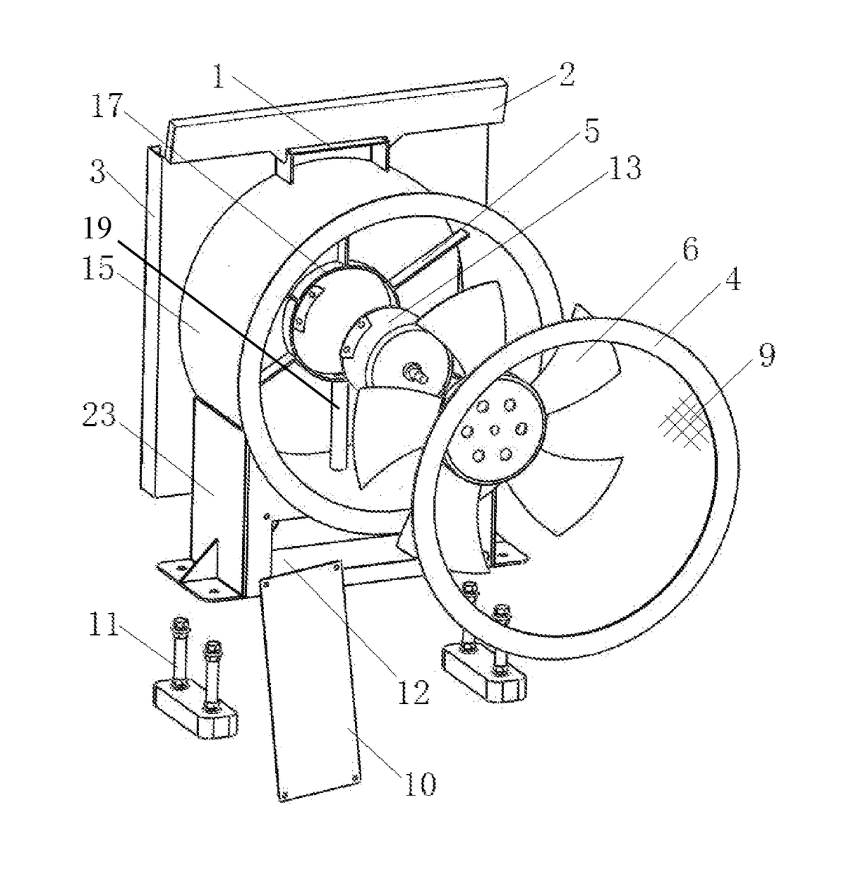
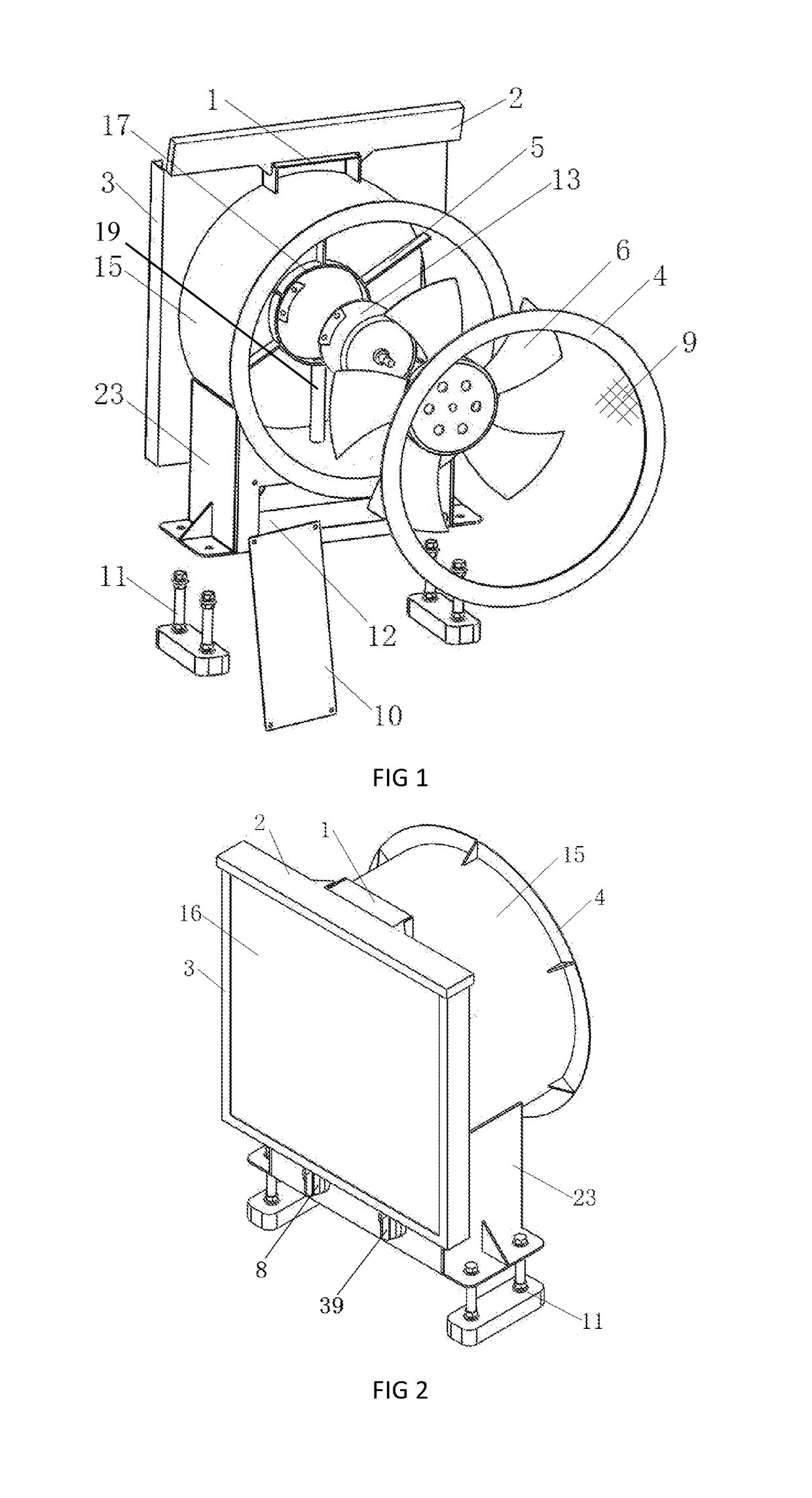
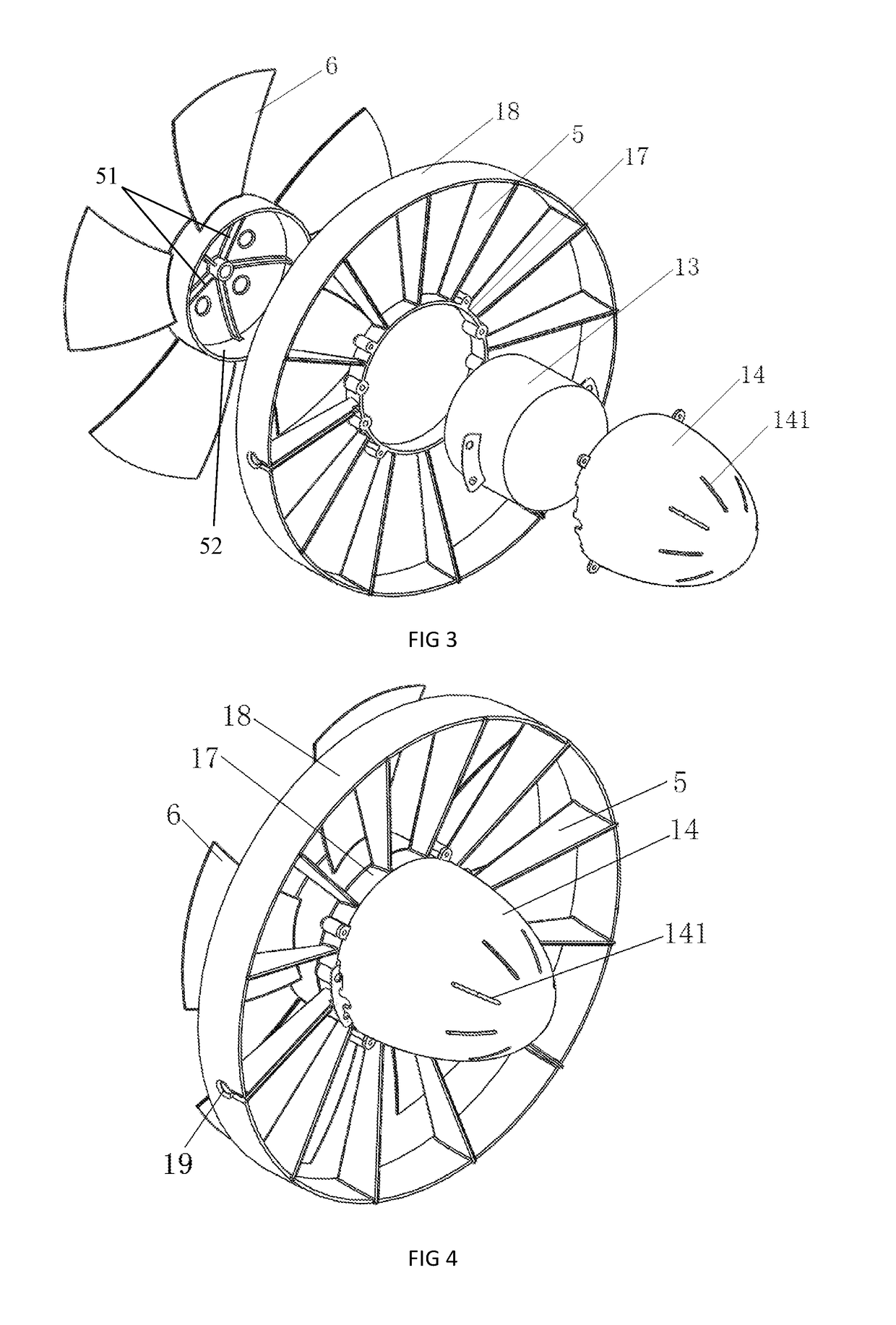
[0050]1—carry handle; 2—lid; 3—filter housing; 4—docking ring; 5—motor supports / guide vanes; 6—fan; 7—inlet; 8—speed adjustment knob; 9—prefilter; 10—electrical control box cover; 11—height and tilt adjuster; 111—height adjustment mechanism; 112—tilt adjustment mechanism; 12—electrical control box; 13—motor; 14—motor cover; 141—air vents (on the motor cover); 15—housing; 16—filter; 17—inner ring; 18—outer ring; 19—electrical conduit; 20—wind-blocking sheet; 21—window frame; 22—damper / stiffener; 23—seat; 24—diffuser; 25—hub; 28—blade leading edge; 29—blade trailing edge; 30—blade root; 31—blade tip; 32—blade airfoils; 33—hub ring; 34—hub dome; 341—vents (on the hub dome); 35—air inlet hole; 36—connecting ring; 37—safety cage; 38—hose; 39—timer control knob; 40—w...


PUM

PropertyMeasurementUnit
diameteraaaaaaaaaa
diameteraaaaaaaaaa
diameteraaaaaaaaaa

Abstract

An air purifier system characterized by a housing, a fan, and a motor, as well as a docking ring located at the outer edge of the inlet side of the air purifier system, a seat below the housing, a prefilter or barrier upstream of the fan, and a filter downstream of the fan. An air purifier system characterized by an upstream-to-downstream airflow path that includes an axial fan, a diffuser, and a filter, in that relative order, with an electric motor held along the centerline of the housing by one or more supports and / or guide vanes. A docking ring that facilitates attachment of a screen-like, mesh-like, cloth-like, or paper-like filter to a machine capable of air purification, characterized by having a large hole through which air passes and by attachment to the machine utilizing any tongue and groove system, for which installation and removal of the docking ring is achieved, in whole or in part, by rotation of said docking ring relative to the machine.

Description

CROSS-REFERENCE TO RELATED APPLICATIONS[0001]This application is a continuation-in-part of International Application PCT / CN2016 / 098851, with an international filing date of Sep. 13, 2016, now pending, which claims priority to People's Republic of China Application (CN) 201510581044.2, with a filing date of Sep. 13, 2015.STATEMENT REGARDING FEDERALLY SPONSORED RESEARCH OR DEVELOPMENT[0002]Not ApplicableTHE NAMES OF THE PARTIES TO A JOINT RESEARCH AGREEMENT[0003]Not ApplicableREFERENCE TO A “SEQUENCE LISTING,” A TABLE, OR A COMPUTER[0004]Not ApplicableBACKGROUND OF THE INVENTION(1) Field of Invention[0005]The present invention relates to the field of air purification.(2) Description of Related Art[0006]Existing air purifiers use different techniques to remove particulate matter from the air, including placing a positive or negative charge on a particle and the reverse charge on a collection plate. These ionic air purifiers are efficient, but ionized particles escape from into the air ...

Claims


Application Information

Patent Timeline
Patent Type & Authority Applications(United States)
IPC IPC(8): F04D29/70F04D25/12E06B7/02F24F7/013B01D46/52B01D46/10B01D46/00F24F8/108F24F8/158
CPCF04D29/703F04D25/12E06B7/02F24F7/013B01D46/521B01D46/10B01D46/0023B01D46/0045F04D29/541F04D25/06E06B2007/023F04D25/08F24F13/28F24F13/20F24F13/32F24F7/007F24F2013/205F24F2221/38F04D29/542F04D29/5806F04D29/329F04D29/662F24F8/108F24F8/158F24F8/80F04D29/547F04D29/70B01D46/62
Inventor RANDALL, RYAN MICHAEL
Owner QINGDAO RANDALL AERODYNAMICS ENG LLC
Why Eureka
Try Eureka