Cleaning of Depth Data by Elimination of Artifacts Caused by Shadows and Parallax

Active Publication Date: 2018-07-19
SEIKO EPSON CORP
View PDF0 Cites 41 Cited by
  • Summary
  • Abstract
  • Description
  • Claims
  • Application Information

AI Technical Summary

Benefits of technology

[0026]Further preferably, positions of each texture data point along each line of texture data are assigned an incremental numerical identifier increasing along the first direction; and the subsequent depth data point is the first encountered depth data point in the first direction whose mapped texture data point has a numerical identifier higher than the numerical identifier of the texture data point of the texture data point mapped to the current depth data point.
[0027]Additionally, positions of each texture

Problems solved by technology

As a result, it has heretofore been very difficult, and indeed not practical, to produce renditions of computer generated 3D items within real-life scene images in real time.
It

Method used


Image

  • Cleaning of Depth Data by Elimination of Artifacts Caused by Shadows and Parallax
  • Cleaning of Depth Data by Elimination of Artifacts Caused by Shadows and Parallax
  • Cleaning of Depth Data by Elimination of Artifacts Caused by Shadows and Parallax

Examples


Example

[0066]The present, real-time, artificial / augmented reality generating system / method is herein termed a “Holocam Orb System” because of its use of what are herein termed “Holocam Orbs”, each of which is an independent data gathering device (i.e. independent sensing apparatus incorporating multiple sensors) that gathers (real-life) scene information (preferably including audio data and 2D / 3D imaging data) from its respective field-of-view (FOV). Information from multiple Holocam Orbs is combined within a computing system (e.g. a general purpose computer or a specialized computer or other data processing device) to create a multi-view 3D artificial reality scene that may surround a viewer standing within the scene.

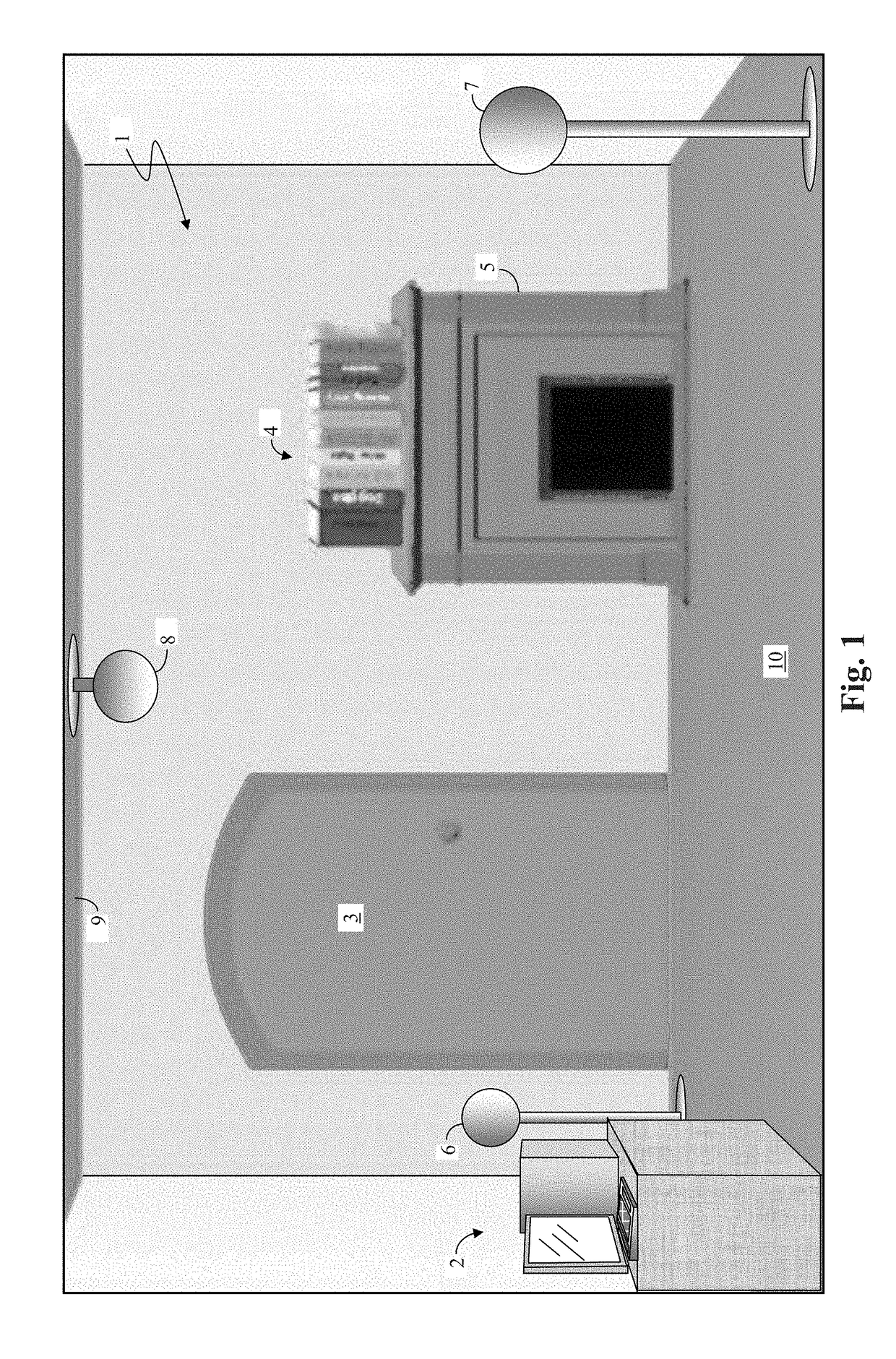
[0067]For example, FIG. 1 illustrates an exemplary, real-world scene consisting of a room 1 with a computer 2, a door 3, and books 4 on a chimney 5. Additionally, three figuratively illustrated Holocam Orbs 6, 7, and 8 are shown distributed within room 1. Holocam Orb 6 prefer...


PUM


Abstract

Multiple Holocam Orbs observe a real-life environment and generate an artificial reality representation of the real-life environment. Depth image data is cleansed of error due to LED shadow by identifying the edge of a foreground object in an (near infrared light) intensity image, identifying an edge in a depth image, and taking the difference between the start of both edges. Depth data error due to parallax is identified noting when associated text data in a given pixel row that is progressing in a given row direction (left-to-right or right-to-left) reverses order. Sound sources are identified by comparing results of a blind audio source localization algorithm, with the spatial 3D model provided by the Holocam Orb. Sound sources that corresponding to identifying 3D objects are associated together. Additionally, types of data supported by a standard movie data container, such as an MPEG container, is expanding to incorporate free viewpoint data (FVD) model data. This is done by inserting FVD data of different individual 3D objects at different sample rates into a single video stream. Each 3D object is separately identified by a separately assigned ID.

Description

BACKGROUNDField of Invention[0001]The present invention relates to the fields of virtual reality and augmented reality. More specifically it relates method of identifying and removing error from depth images (or depth data) to create a three-dimensional computer simulation / emulation / model of a real, local environment.Description of Related Art[0002]Virtual reality, or artificial reality, which may include augmented reality, relates to the use of computers and three-dimensional (3D) imaging techniques to create a 3D representation within a computer of a real-life (or seemingly real-life) scene. Various 3D observation tools may be used. Examples of such observation tools may include stereo imaging equipment (e.g. 3D cameras) or time-of-flight capturing units, which may use infrared sensors or laser sensors to obtain 3D depth information.[0003]Typically, one wishes to anchor computer generated 3D items to a video (or still) image portrayal of the generated 3D items within an imaged (3D...

Claims


Application Information

Patent Timeline
IPC IPC(8): H04N13/00H04N13/02G06T7/521G06T7/13
CPCG06T7/521G06T7/13G06T2207/10028H04N13/254H04N13/122H04N13/271H04N13/128G06T5/005G06T5/50G06T2207/10048G06T2207/10024H04N13/207
Inventor MOGALAPALLI, VIVEKMORAVEC, IVOMANNION, MICHAEL JOSEPH
Owner SEIKO EPSON CORP
Why Eureka
Try Eureka