Drive apparatus

a technology of drive apparatus and drive shaft, which is applied in the direction of coupling contact member, coupling device connection, transportation and packaging, etc., can solve the problems of difficult non-destructive disassembly electrical production of the drive apparatus, and substrate requirements special and large-sized equipment, so as to achieve the effect of reducing the production cost of the drive apparatus

Active Publication Date: 2018-08-02
DENSO CORP
View PDF14 Cites 5 Cited by
  • Summary
  • Abstract
  • Description
  • Claims
  • Application Information

AI Technical Summary

Benefits of technology

[0009]The above structure eliminates the need for soldering or welding to achieve an electrical connection of the motor and the control unit. Specifically, the electrical connection is accomplished by inserting the first terminal into the second terminal, thus eliminating the need for a special and large-sized equipment and resulting in a decrease in production cost of the drive apparatus.
[0010]The non-destructive disassembling of the motor and the control unit is achieved by disengaging them from each other to remove the second terminal from the first terminal. Therefore, if a defect in the drive apparatus is found after assembled, only one of the motor and the control unit which has the defect can be replaced with a new one without having to discard the whole of the drive apparatus.

Problems solved by technology

Production of the drive apparatus in which the electrical leads are soldered or welded to the substrate requires special and large-sized equipment.
Once assembled, the drive apparatus is difficult to disassemble in a non-destructive manner.
If, therefore, some fault of the drive apparatus is found after the drive apparatus is assembled, it needs to dispose the whole of the drive apparatus.
Specifically, the electrical connection is accomplished by inserting the first terminal into the second terminal, thus eliminating the need for a special and large-sized equipment and resulting in a decrease in production cost of the drive apparatus.

Method used


Image

  • Drive apparatus
  • Drive apparatus
  • Drive apparatus

Examples


first embodiment

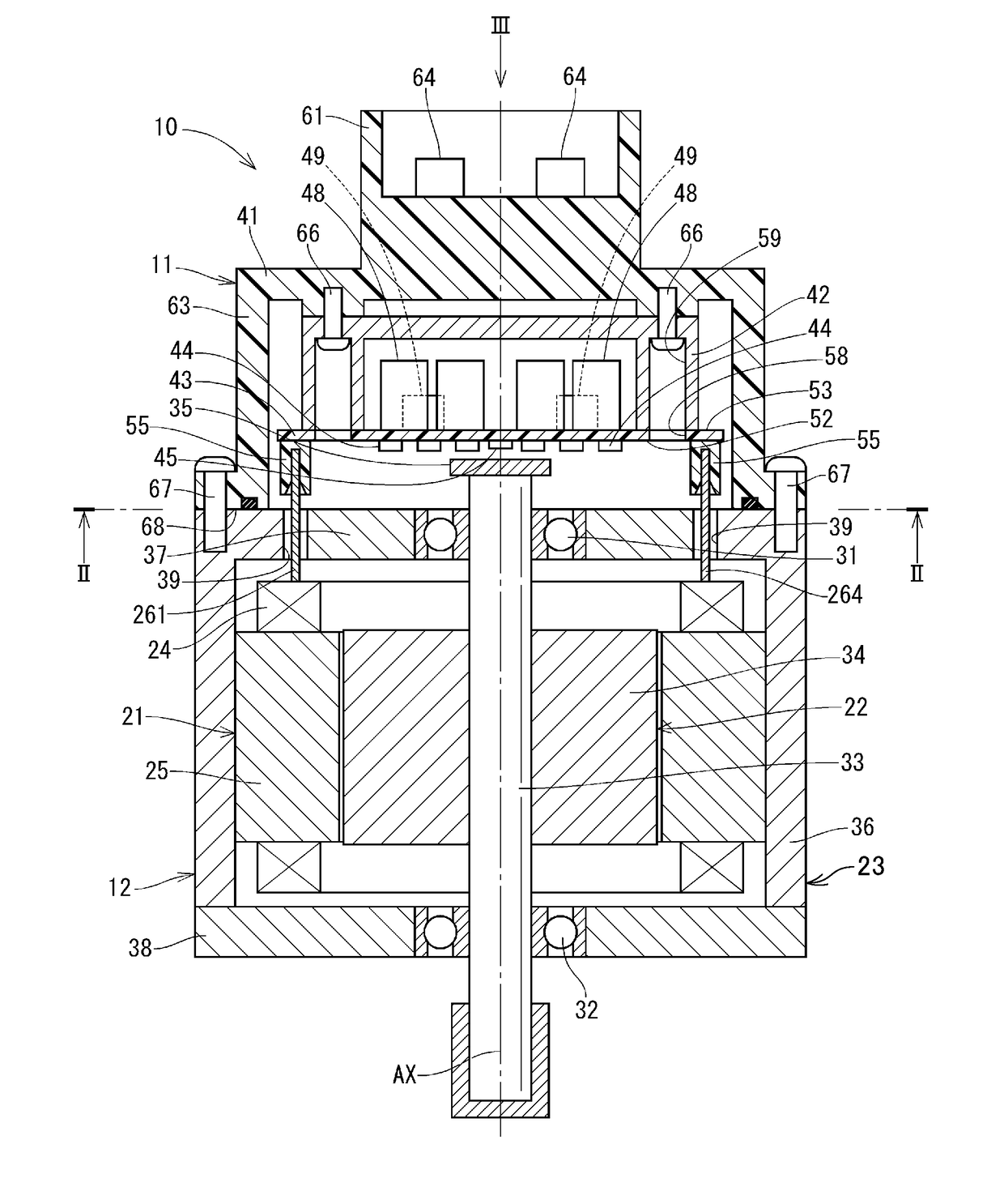
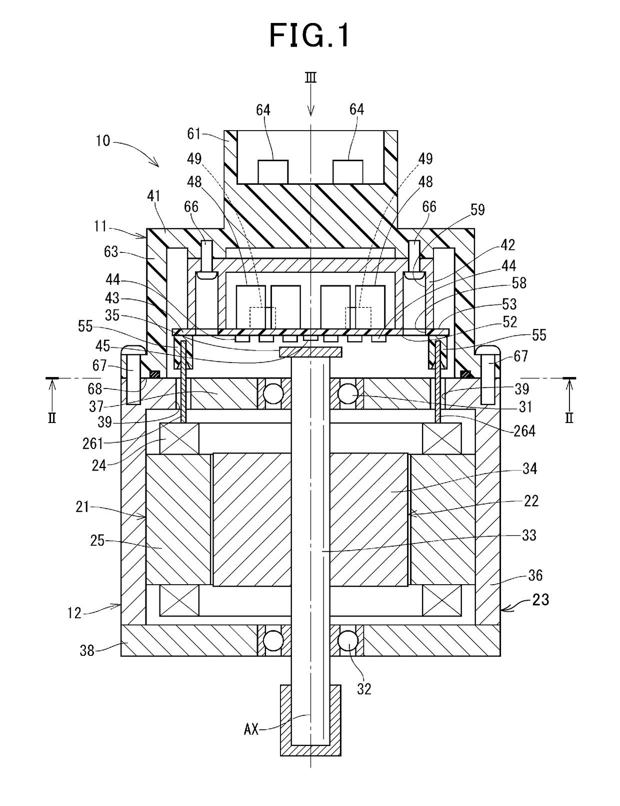
[0029]FIG. 1 illustrates the drive apparatus 10 according to the first embodiment. The drive apparatus 10 is used as a drive source for an electrical power steering system working to assist a steering operation of a drive of a vehicle.

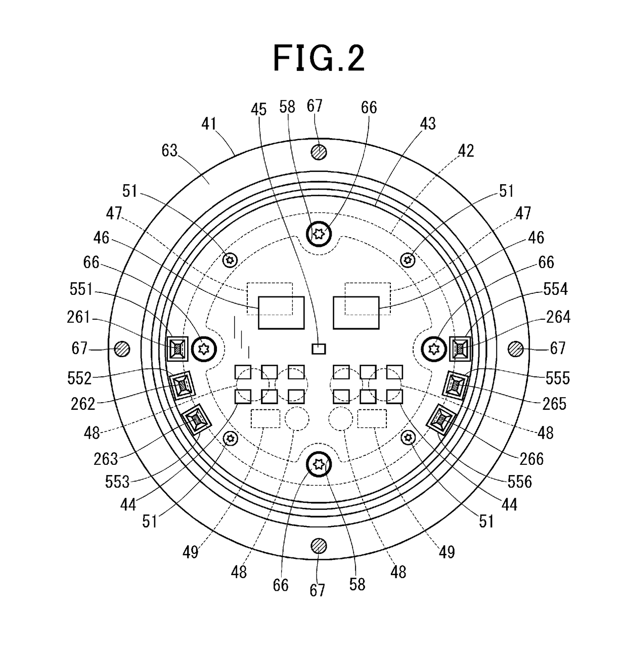
[0030]The overall structure of the drive apparatus 10 will be described below with reference to FIGS. 1 and 2.

[0031]The drive apparatus 10 is designed as a motor-integrated driver which has the electrical the motor 12 and the control unit 11 disposed therein.

[0032]The motor 12 is, as clearly illustrated in FIGS. 1 and 2, implemented by a three-phase brushless motor and includes the stator 21, the rotor 22, and the housing 23 in which the stator 21 and the rotor 22 are disposed.

[0033]The stator 21 is equipped with the stator core 24 secured to the housing 23, and two three-phase coils 25 arranged on the stator core 24. Three phase windings of one of the coils 25 have electrical lead 261, 262, and 263 extending therefrom, respectively. Similarly, three p...

second embodiment

[0060]FIG. 6 illustrates the drive apparatus 10 according to the second embodiment.

[0061]The drive apparatus 10 includes the cover 71 equipped with the external connectors 61 and 62, and the covering portion 72. The covering portion 72 is not formed in a cup shape, but in a circular disc shape. The motor 12 is equipped with the housing 73 which includes the hollow cylindrical extension 74 which protrudes from the first frame end 37 toward the control unit 11. The covering portion 72 is secured to the cylindrical extension 74 using screws 67.

third embodiment

[0062]FIG. 7 illustrates the drive apparatus 10 according to the third embodiment.

[0063]The drive apparatus 10 is equipped with the cover 75 which has the covering portion 76. The covering portion 76 is not formed in a cup shape, but in a circular disc shape. The heat sink 77 is fit in the cylindrical extension 74 and has the flange 78 extending in the radial direction. The heat sink 77 is attached to the covering portion 76 using the screws 66 and also secured to the cylindrical extension 74 using the screws 67.

[0064]As apparent from the above discussion, the control unit 11, unlike the above embodiments, has the heat sink 77 fixed on the housing 73. This also achieves a mechanical joint of the cover 75 of the control unit 11 to the housing 73.

[0065]The heat sink 77 is die-casted with aluminum and has a precise shape. This results in increased accuracy in positioning the control unit 11 and the motor 12 and also facilitates dissipation of heat generated by the control unit 11.


PUM


Abstract

A drive apparatus is provided which includes a motor and a control unit. The control unit has a heat sink secured to a cover. The motor is equipped with leads extending toward the control unit through a housing. The control unit has a substrate which is equipped with connectors detachably joined to the leads, thereby eliminating soldering or welding to achieve an electrical connection of the motor and the control unit. Such a connection is accomplished by inserting the leads into the connectors, thus eliminating the need for a special and large-sized equipment and resulting in a decrease in production cost of the drive apparatus. The non-destructive disassembling of the motor and the control unit is achieved by disengaging them from each other to remove the second terminal from the first terminal.

Description

CROSS REFERENCE TO RELATED DOCUMENT[0001]The present application claims the benefit of priority of Japanese Patent Application No. 2017-15246 filed on Jan. 31, 2017 the disclosure of which is incorporated herein by reference.BACKGROUND1 Technical Field[0002]The invention relates generally to a drive apparatus for use in an electrical power steering system which electrically assists a steering operation of a driver of vehicles such as automobiles.2 Background Art[0003]Drive apparatuses are shown which are equipped with an electrical motor and a control unit working to control an operation of the motor. Japanese Patent First Publication No. 2017-017866 teaches such a type of drive apparatus designed to achieve an electrical connection between the motor and the control unit using electrical leads which extend from the motor to the control unit through a motor housing. The electrical leads are soldered to conductive portions on a substrate of the control unit.[0004]Production of the dri...

Claims


Application Information

Patent Timeline
Patent Type & Authority Applications(United States)
IPC IPC(8): H02K5/22H02K9/00H02K11/33B62D5/04
CPCH02K5/225H02K11/33H02K9/00B62D5/0406H01R13/02H01R13/631H02K29/00H02K29/06H01R2201/10H02K9/227H02K11/215
Inventor YAMAMOTO, NAOHIRO
Owner DENSO CORP
Why Eureka
Try Eureka