Method and Device for Detecting a Neural Response in Neural Measurements

a neural response and neural measurement technology, applied in the field of neural response detection, can solve the problems of difficult task, presenting a significant obstacle to isolating or even detecting the much smaller cap signal of interest, and the impracticality of implant system, so as to improve the resistance to corruption and improve the determination

Active Publication Date: 2018-08-16
SALUDA MEDICAL PTY LTD
View PDF3 Cites 53 Cited by
  • Summary
  • Abstract
  • Description
  • Claims
  • Application Information

AI Technical Summary

Benefits of technology

[0035]In some embodiments the detector output is used in a closed loop feedback circuit to control neuromodulation, for example in conjunction with the techniques of International Patent Publication No. WO 2012 / 155188, by the present applicant, the content of which is incorporated herein by reference. Such embodiments may thus effect feedback control of electrical stimuli with improved resistance to corruption by the patient's independent motor activity and / or peripheral stimuli.
[0036]In some embodiments the method may be repeated in order to obtain a plurality of ratios resulting from repeated application of a given stimulus. The plurality of ratios may then give a probabilistic indication of the neural response decay to improve the determination of whether a locally evoked response is present.

Problems solved by technology

However, this can be a difficult task as an observed CAP signal component in the neural measurement will typically have a maximum amplitude in the range of microvolts.
In contrast a stimulus applied to evoke the CAP is typically several volts and results in electrode artifact, which manifests in the neural measurement as a decaying output of several millivolts partly or wholly contemporaneously with the CAP signal, presenting a significant obstacle to isolating or even detecting the much smaller CAP signal of interest.
For example, to resolve a 10 uV CAP with 1 uV resolution in the presence of an input 5 V stimulus requires an amplifier with a dynamic range of 134 dB, which is impractical in implant systems.
As the neural response can be contemporaneous with the stimulus and / or the stimulus artefact, CAP measurements present a difficult challenge of measurement amplifier design.
In practice, many non-ideal aspects of a circuit lead to artefact, and as these mostly have a decaying exponential appearance that can be of positive or negative polarity, their identification and elimination can be laborious.
The difficulty of this problem is further exacerbated when attempting to implement CAP detection in an implanted device.

Method used


Image

  • Method and Device for Detecting a Neural Response in Neural Measurements
  • Method and Device for Detecting a Neural Response in Neural Measurements
  • Method and Device for Detecting a Neural Response in Neural Measurements

Examples


Embodiment Construction

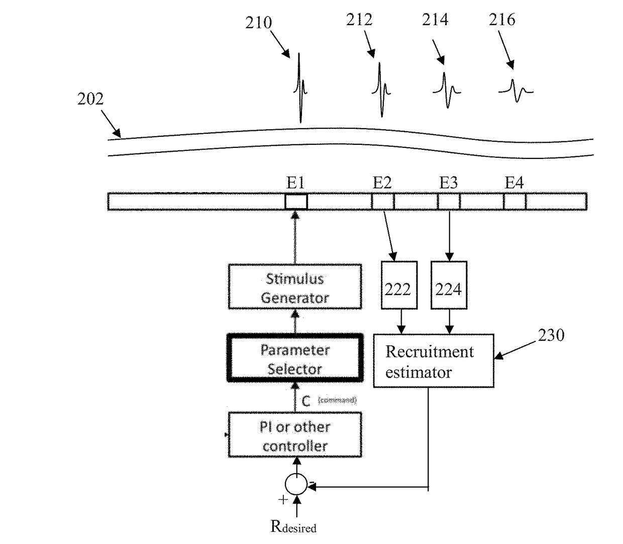
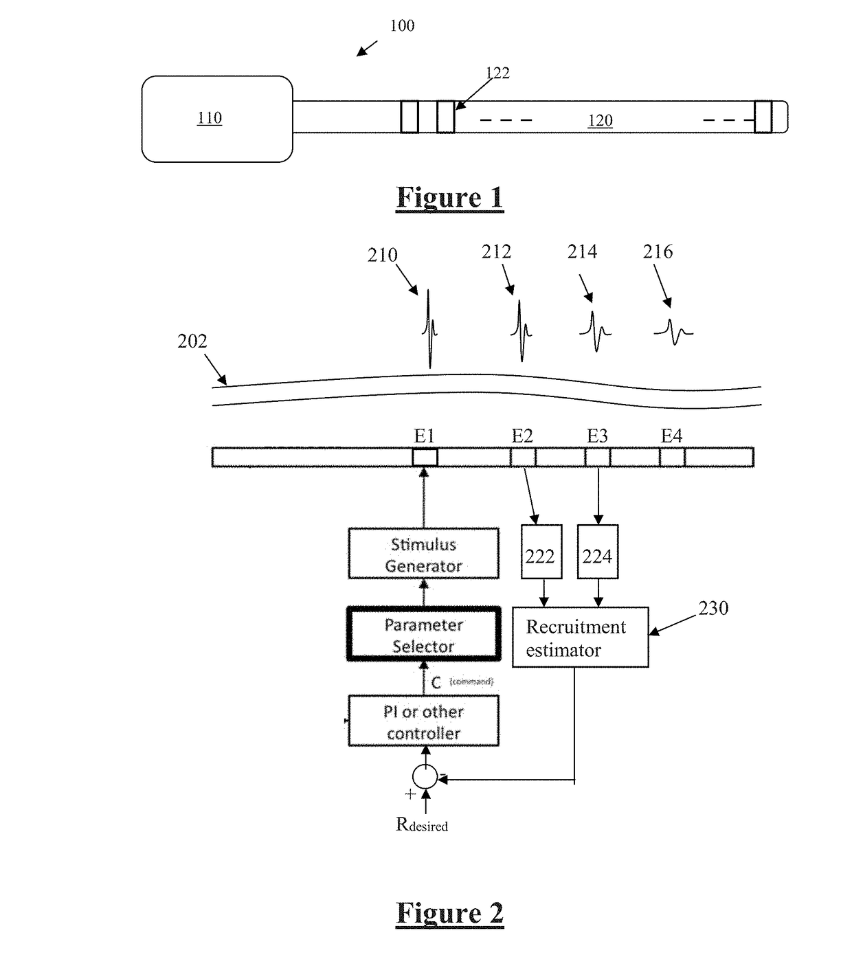
[0050]FIG. 1 illustrates an implantable device 100 suitable for implementing the present invention. Device 100 comprises an implanted control unit 110, which controls application of neural stimuli, and controls a measurement process for obtaining a measurement of a neural response evoked by the stimuli from each of a plurality of electrodes. The control unit 110 includes a processor and a storage memory (or other storage device(s), not shown) for carrying out the method of the present embodiment of the invention. Device 100 further comprises an electrode array 120 consisting of a linear array of electrodes 122, each of which may be selectively used as either the stimulus electrode or sense electrode, or both.

[0051]FIG. 2 is a schematic of a feedback controller implemented by the control unit 110, based on recruitment. An important component of such feedback control is a recruitment estimator 230, which performs the difficult task of detecting whether an evoked neural response is pre...


PUM


Abstract

A method is provided for processing a neural measurement obtained in the presence of noise, in order to detect whether a locally evoked neural response is present in the neural measurement. A first neural measurement is obtained from a first sense electrode. A second neural measurement is contemporaneously obtained from a second sense electrode spaced apart from the first electrode along a neural pathway of the neural response. A neural response decay is determined, being a measure of the decay in the neural response from the first sense electrode to the second sense electrode. A ratio of the neural response decay to an amplitude normalising term is calculated. From the ratio it is determined whether a locally evoked neural response is present in the neural measurement.

Description

CROSS-REFERENCE TO RELATED APPLICATIONS[0001]This application claims the benefit of Australian Provisional Patent Application No. 2014904595 filed 17 Nov. 2014, which is incorporated herein by reference.TECHNICAL FIELD[0002]The present invention relates to detection of a neural response, such as a neural response caused by a stimulus. In particular the present invention relates to detection of a compound action potential by using one or more electrodes implanted proximal to the neural pathway to obtain a neural measurement.BACKGROUND OF THE INVENTION[0003]Electrical neuromodulation is used or envisaged for use to treat a variety of disorders including chronic pain, Parkinson's disease, and migraine, and to restore function including but not limited to hearing and motor function. A neuromodulation system applies an electrical pulse to neural tissue in order to generate a therapeutic effect. Such a system typically comprises an implanted electrical pulse generator, and a power source ...

Claims


Application Information

Patent Timeline
Patent Type & Authority Applications(United States)
IPC IPC(8): A61B5/04A61N1/36G16H40/63
CPCA61B5/04014A61B5/04001A61N1/36135G16H40/63A61B5/7203A61B5/7214A61B5/7282A61B5/407A61B5/4836A61B5/24A61B5/316A61B5/389A61B5/388
Inventor PARKER, JOHN LOUISOBRADOVIC, MILAN
Owner SALUDA MEDICAL PTY LTD
Why Eureka
Try Eureka