Forming method

a technology of shear forming and forming plate, which is applied in the field of shear forming plate, can solve the problems of substantial increase in the cost of the shear forming process, and achieve the effect of improving the fatigue properties of the shear formed pla

Inactive Publication Date: 2018-08-16
ROLLS ROYCE PLC
View PDF2 Cites 2 Cited by
  • Summary
  • Abstract
  • Description
  • Claims
  • Application Information

AI Technical Summary

Benefits of technology

[0012]Indeed the fatigue properties of the shear formed article are improved in line with the co

Problems solved by technology

This has led to a situation whereby grinding on both sides of the sheet is often stipulated

Method used


Image

  • Forming method
  • Forming method
  • Forming method

Examples


Embodiment Construction

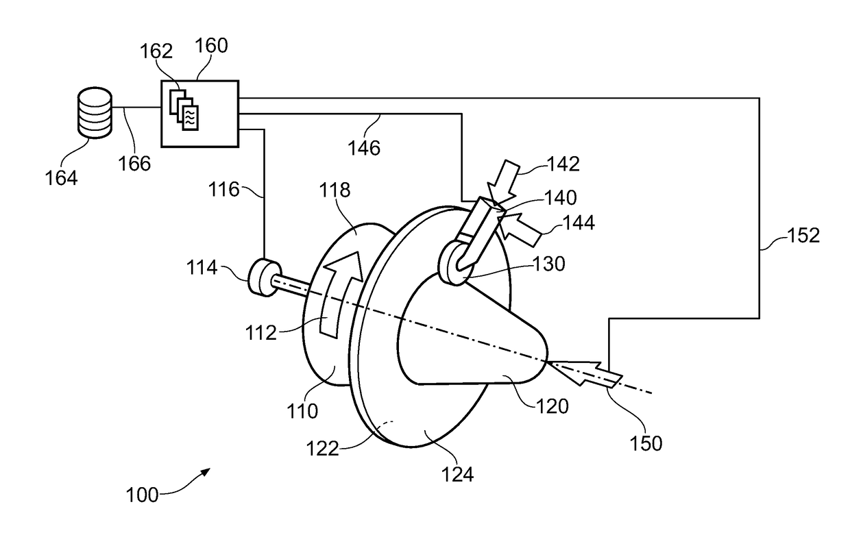
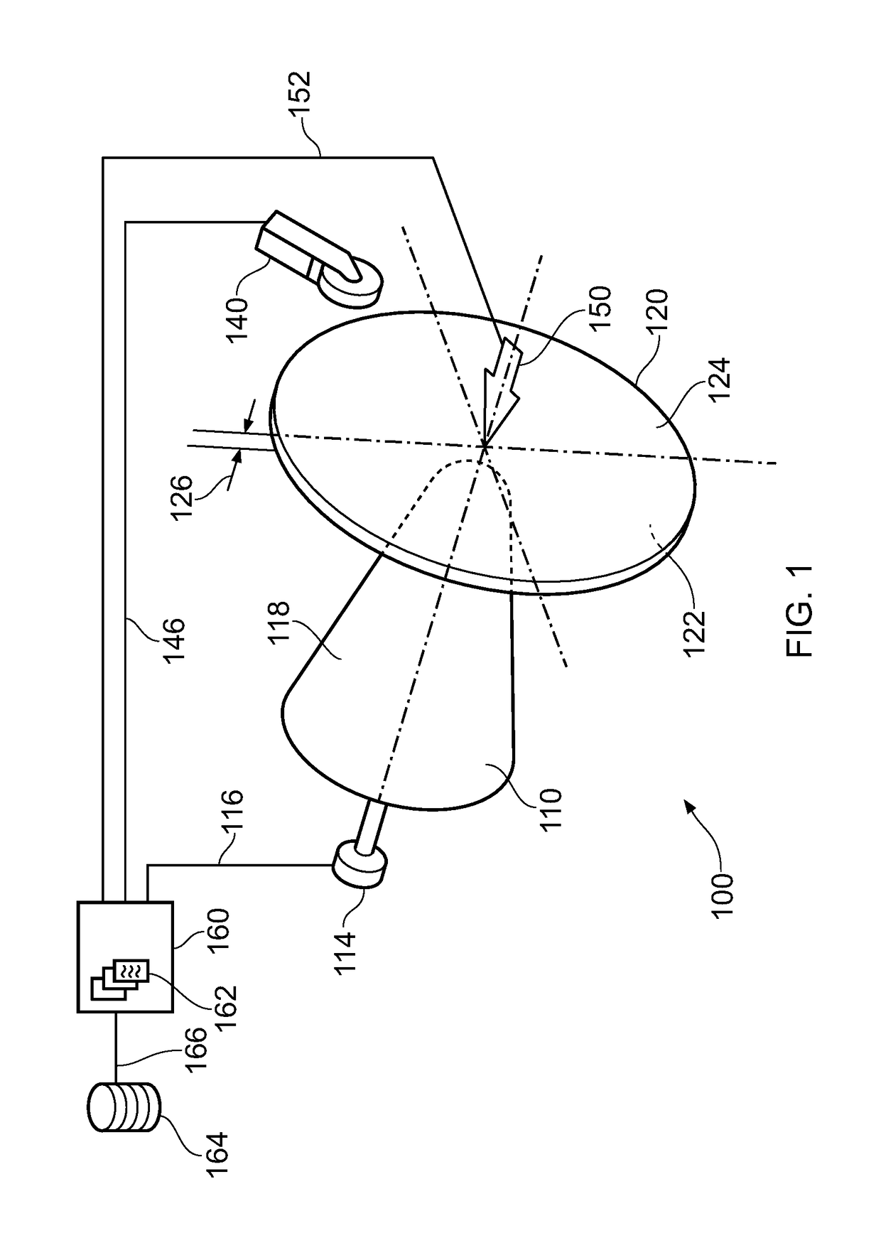
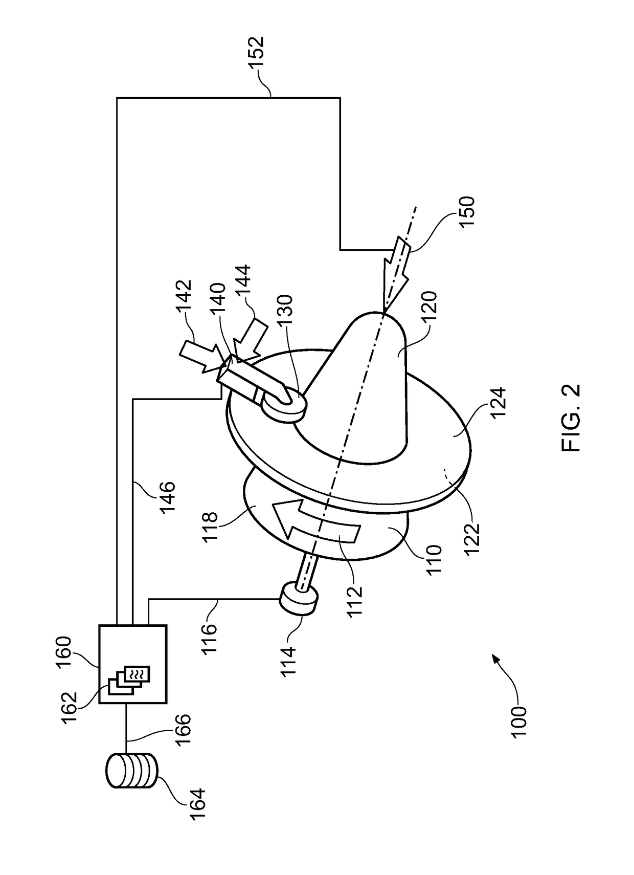
[0039]Referring to FIGS. 1 and 2, a shear forming apparatus that is capable of carrying out the method of the present disclosure is designated generally by the reference numeral 100.

[0040]The shear forming apparatus 100 comprises a mandrel 110 that can be rotated in a direction of rotation 112 by means of a rotary actuator 114. The mandrel 110 has a generally radially outwardly facing surface 118. This radially outwardly facing surface 118 is formed as an inverse of the desired surface profile of the finished article resulting from the shear forming process.

[0041]A pre-formed metallic sheet blank 120 is clamped against the distal end of the mandrel 110 by a clamping force 150. In this way the rotation 112 of the mandrel is transmitted to the sheet blank 120 that rotates co-operatively with the mandrel 110.

[0042]The sheet blank 120 is provided with a first surface 122 and an opposite second surface 124. In the present disclosure, the first surface 122 is subjected to a surface modifi...


PUM

PropertyMeasurementUnit
Surface roughnessaaaaaaaaaa

Abstract

A method of shear forming a component comprises the steps of:
    • (i) providing a pre-formed metallic sheet blank, the sheet blank having a first surface and an opposite second surface, the perpendicular separation between the first surface and the second surface defining a thickness of the sheet blank;
    • (ii) applying a surface modification process to the first surface of the sheet blank to reduce a surface roughness of the first surface to a first predetermined roughness value;
    • (iii) positioning the second surface of the sheet blank against a mandrel; and
    • (iv) applying a roller to the first surface of the sheet blank in a shear forming operation to form the sheet blank into the component.

Description

CROSS-REFERENCE RELATED APPLICATIONS[0001]This disclosure claims the benefit of UK Patent Application No. GB 1702463.9, filed on 15 Feb. 2017, which is hereby incorporated herein in its entirety.FIELD OF THE DISCLOSURE[0002]The present disclosure relates to a method of shear forming and particularly, but not exclusively, to a method of shear forming components for a gas turbine engine.BACKGROUND OF THE DISCLOSURE[0003]Shear forming has been used to produce conical parts from sheet and plate material for many years. Shear forming is a cold forming technology whereby a flat metal plate blank (or ‘pre-form’) is mounted onto a rotating mandrel (typically having a conical surface profile) and the material is made to flow against and up the mandrel by the action of one or more rollers. The final wall thickness is achieved by controlling the gap between the roller and the mandrel so the material is displaced axially, and generally parallel to the axis of rotation.[0004]Sheet material used ...

Claims


Application Information

Patent Timeline
IPC IPC(8): B21B13/10B21B45/00
CPCB21B13/10B21B45/00B21B2205/00B21D22/16B21B1/227B21D22/14
Inventor TUFFS, MARTINJOHNSON, CRAIG A.
Owner ROLLS ROYCE PLC
Why Eureka
Try Eureka