Control apparatus for hybrid vehicle
a control apparatus and hybrid technology, applied in the direction of engine-driven generator propulsion, transportation and packaging, propulsion parts, etc., can solve the problems of unintentional reduction of compensating torque, inability to output appropriate compensating torque, and inability to appropriately suppress torque pulsation, etc., to suppress the influence of internal combustion engine torque fluctuation
- Summary
- Abstract
- Description
- Claims
- Application Information
AI Technical Summary
Benefits of technology
Problems solved by technology
Method used
Image
Examples
first embodiment
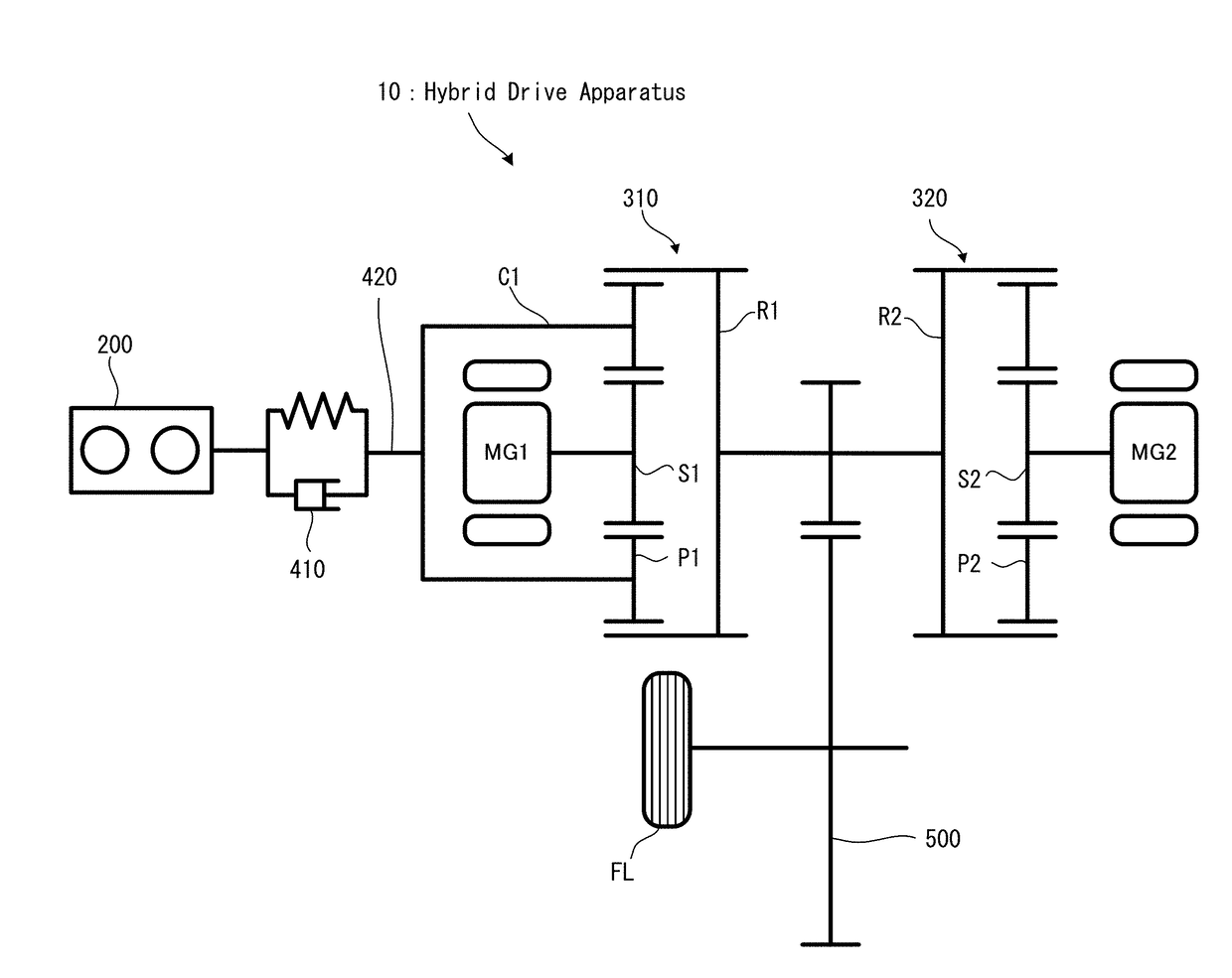
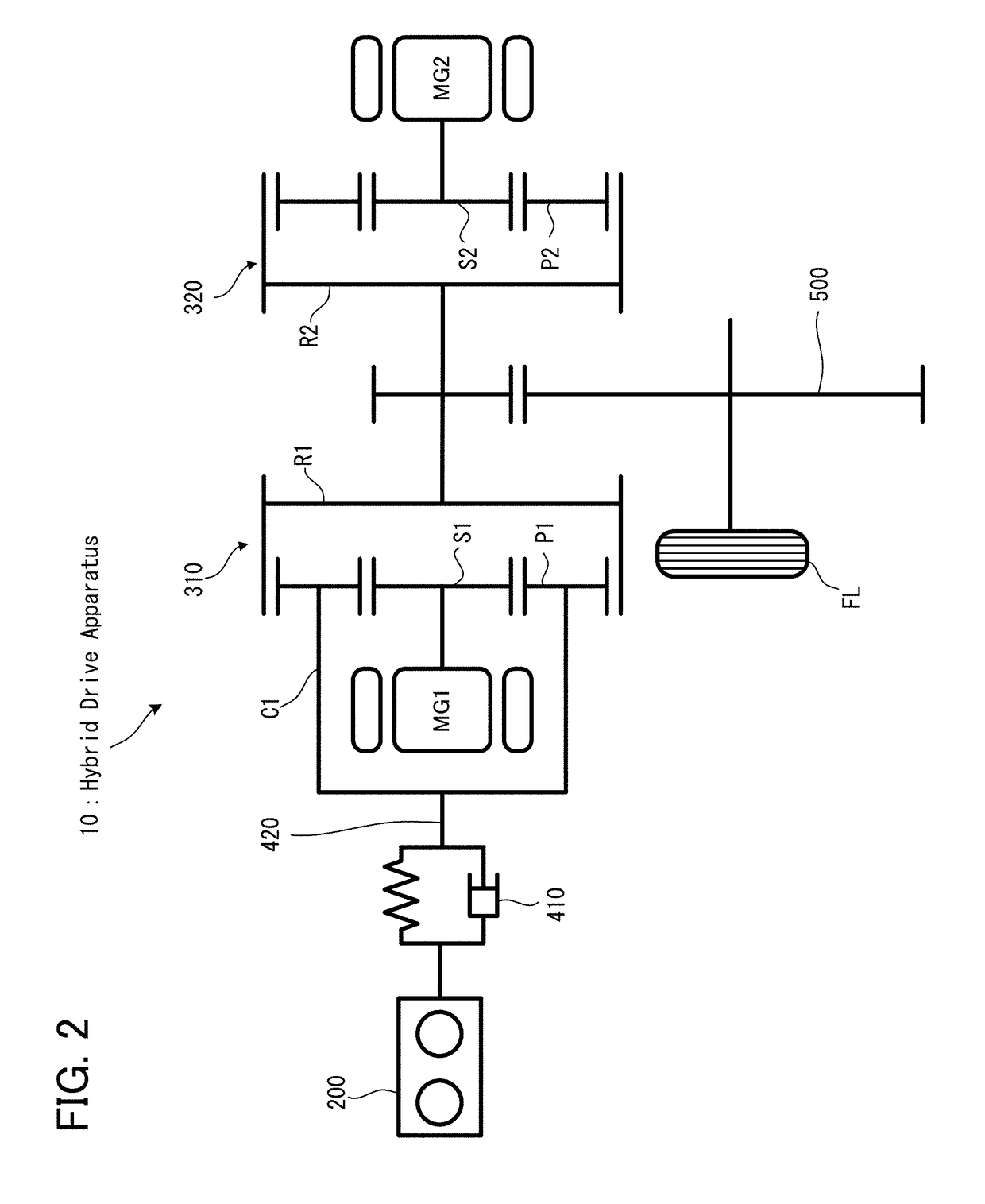
[0027]A control apparatus for a hybrid vehicle according to a first embodiment will be explained with reference to FIG. 1 to FIG. 6.
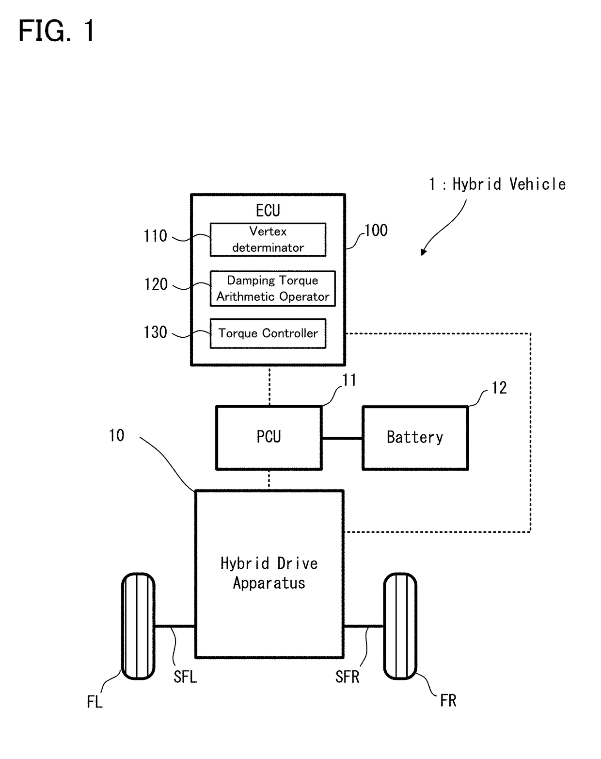
[0028]Firstly, with reference to FIG. 1, an explanation will be given to a configuration of a hybrid vehicle on which the control apparatus for the hybrid vehicle according to the first embodiment is mounted. FIG. 1 is a schematic diagram illustrating an entire configuration of the hybrid vehicle according to the first embodiment;
[0029]As illustrated in FIG. 1, a hybrid vehicle 1 according to the first embodiment is provided with an electronic control unit (ECU) 100, a power control unit (PCU) 11, a battery 12, and a hybrid drive apparatus 10.
[0030]The ECU 100 is one specific example of the “control apparatus for the hybrid vehicle”, and is provided with a central processing unit (CPU), a read only memory (ROM), a random access memory (RAM) and the like. The ECU 100 is an electronic control unit configured to control the operation of each part of the hy...
second embodiment
[0063]Next, a control apparatus for a hybrid vehicle according to a second embodiment will be explained with reference to FIG. 7 and FIG. 8. The second embodiment is different from the first embodiment only in a part of the operation, and is substantially the same as the first embodiment with regard to the other operation and the apparatus configuration. Thus, hereinafter, a different part from the first embodiment already explained will be explained in detail, and an explanation of the same part will be omitted, as occasion demands.
[0064]
[0065]The operation of the control apparatus for the hybrid vehicle according to the second embodiment will be explained in detail with reference to FIG. 7. FIG. 7 is a flowchart illustrating a flow of the operation of the control apparatus for the hybrid vehicle according to the second embodiment. In FIG. 7, the same process steps as those in the first embodiment illustrated in FIG. 4 carry the same reference numerals.
[0066]As illustrated in FIG. ...
third embodiment
[0074]Next, a control apparatus for a hybrid vehicle according to a third embodiment will be explained with reference to FIG. 9 to FIG. 11. The third embodiment is different from the first and second embodiments only in a part of the operation, and is substantially the same as the first and second embodiments with regard to the other operation and the apparatus configuration. Thus, hereinafter, a different part from the first and second embodiments already explained will be explained in detail, and an explanation of the same part will be omitted, as occasion demands.
[0075]
[0076]The operation of the control apparatus for the hybrid vehicle according to the third embodiment will be explained in detail with reference to FIG. 9. FIG. 9 is a flowchart illustrating a flow of the operation of the control apparatus for the hybrid vehicle according to the third embodiment. In FIG. 9, the same process steps as those in the first embodiment illustrated in FIG. 4 carry the same reference numera...
PUM
 Abstract
Description
Claims
Application Information
 - R&D
- Intellectual Property
- Life Sciences
- Materials
- Tech Scout
- Unparalleled Data Quality
- Higher Quality Content
- 60% Fewer Hallucinations
Browse by: Latest US Patents, China's latest patents, Technical Efficacy Thesaurus, Application Domain, Technology Topic, Popular Technical Reports.
© 2025 PatSnap. All rights reserved.Legal|Privacy policy|Modern Slavery Act Transparency Statement|Sitemap|About US| Contact US: help@patsnap.com


