Internal-combustion-engine combustion state detecting apparatus

a technology of internal combustion engine and detection apparatus, which is applied in the direction of engine ignition, machines/engines, etc., can solve the problems that the detection of combustion state based on ion current information cannot be performed during a period, and the inability to detect combustion state using ion curren

Active Publication Date: 2018-08-16
MITSUBISHI ELECTRIC CORP
View PDF1 Cites 0 Cited by
  • Summary
  • Abstract
  • Description
  • Claims
  • Application Information

AI Technical Summary

Benefits of technology

[0013]A combustion state detecting apparatus according to the present invention includes a circulation unit that is configured in such a way that while a spark discharge is produced in an ignition plug, a primary winding is short-circuited so that a circulation path including the primary winding is formed and a circulation current control unit that is configured in such a way as to control a circulation current flowing in the circulation path; thus, the spark discharge is interrupted by the circulation unit and during the interruption of the spark discharge, the circulation current control unit controls the circulation current in such a way that the changing amount of the value of the electric current flowing in the primary winding is decreased or the current value becomes substantially constant, so that comprehension of the combustion state, based on the detection of an ion current, can accurately be performed in a wide operation region of an internal combustion engine.

Problems solved by technology

However, in the case where as described above, an ignition plug is utilized as an ion current detection probe, detection of the combustion state by use of an ion current cannot be performed during a period of spark discharging through the ignition plug of an ignition apparatus, due to the electric current generated by the spark discharging.
Moreover, in the case where the speed of combustion inside a cylinder is high because for example, the operation condition of the internal combustion engine is high-speed-rotation and high-load, the period from a time when ignition is started to a time when generation of ions produced through combustion ends becomes short; thus, as disclosed also in Patent Document 2, in the case where the speed of combustion inside a cylinder is high, most of the generation period of ions produced through combustion is embedded in the spark discharging period; as a result, there has been a problem that detection of the combustion state based on ion current information is difficult.

Method used


Image

  • Internal-combustion-engine combustion state detecting apparatus
  • Internal-combustion-engine combustion state detecting apparatus
  • Internal-combustion-engine combustion state detecting apparatus

Examples


embodiment 1

[0041]Hereinafter, the internal-combustion-engine combustion state detecting apparatus according to Embodiment 1 of the present invention will be explained. FIG. 3 is a configuration diagram representing the basic configuration of the internal-combustion-engine combustion state detecting apparatus according to Embodiment 1 of the present invention. In Embodiment 1 of the present invention, a single-cylinder internal combustion engine will be explained; however, an internal-combustion-engine combustion state detecting apparatus according to the present invention can be applied also to a multi-cylinder internal combustion engine. In that case, ion current detection apparatuses having the same basic configuration may be provided for the respective cylinders or the two or more cylinders may share a partial configuration element of the combustion state detecting apparatus, such as a circulation current control unit.

[0042]In FIG. 3, the internal-combustion-engine combustion state detectin...

embodiment 2

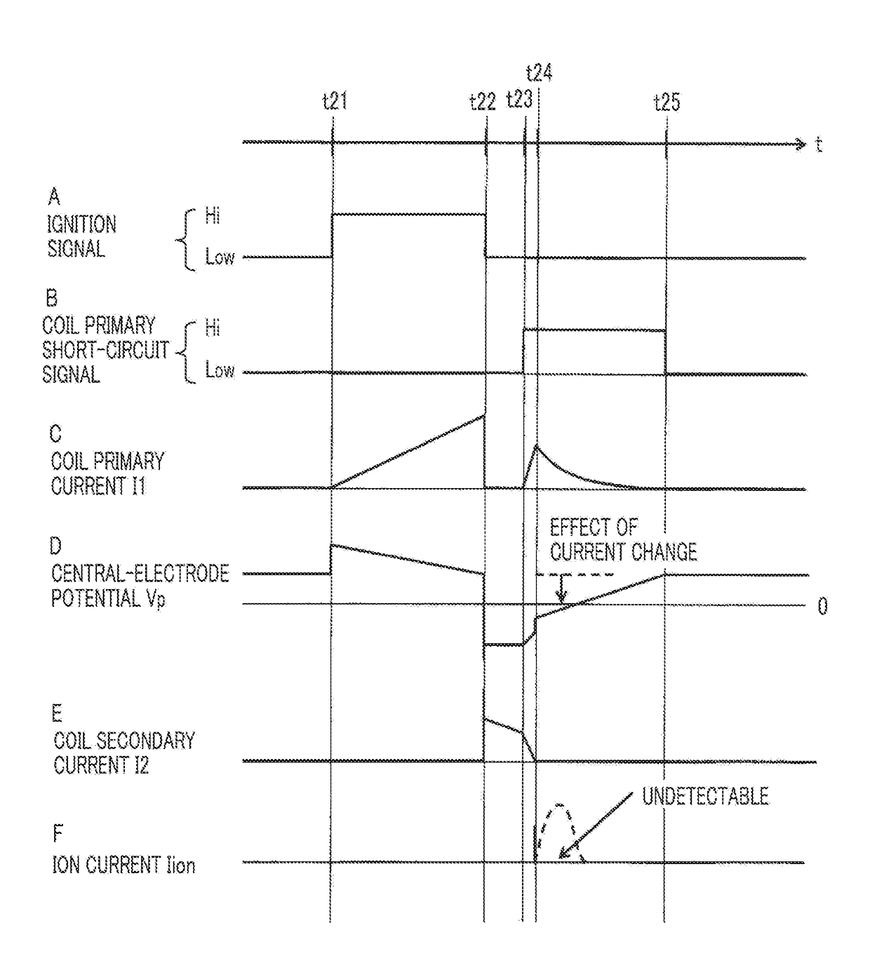
[0078]Next, an internal-combustion-engine combustion state detecting apparatus according to Embodiment 2 of the present invention will be described. In foregoing Embodiment 1, by adjusting the resistance value of the closed circuit for short-circuiting the primary winding L1, the change in the electric current flowing in the primary winding L1 is controlled so as to become small. However, because it is not possible to make zero the resistance components such as the winding resistance of the primary winding L1 and the On-resistance of the switching device, the magnetic flux in the iron core is gradually dissipated and hence the electromotive force decreases; thus, the considerable decrease in the electric current is caused while the discharge is interrupted. Accordingly, the voltage that is generated across the secondary winding L2 during circulation and has a polarity the same as that of the ignition high voltage cannot completely be prevented from being generated. Therefore, as the...

embodiment 3

[0100]Next, an internal-combustion-engine combustion state detecting apparatus according to Embodiment 3 of the present invention will be described. In Embodiment 3 of the present invention, how to determine a circulation current limiting value, which has not been described in detail in Embodiment 2, is specifically explained. FIG. 8 is an example of the basic configuration of an internal-combustion-engine combustion state detecting apparatus according to any one of Embodiment 3 and Embodiment 4, described later. In Embodiment 3, a single-cylinder internal combustion engine will be explained; however, the present invention can be applied also to a multi-cylinder internal combustion engine. In that case, ion current detection apparatuses having the same basic configuration may be provided for the respective cylinders or the two or more cylinders may share a partial configuration element of the combustion state detecting apparatus, such as a circulation current control unit.

[0101]In F...


PUM


Abstract

An internal-combustion-engine combustion state detecting apparatus is configured in such a way as to include a circulation unit that short-circuits a primary winding so as to form a circulation path including the primary winding, while a spark discharge is produced in an ignition plug, and a circulation current control unit that controls a circulation current flowing in the circulation path and in such a way that based on an ion current detected by an ion current detection apparatus, the combustion state of an inflammable fuel-air mixture is detected.

Description

BACKGROUND OF THE INVENTIONField of the Invention[0001]The present invention relates to an internal-combustion-engine combustion state detecting apparatus and particularly to an internal-combustion-engine combustion state detecting apparatus that can accurately detect whether or not there exists combustion in a wide operation region of an internal combustion engine.Description of the Related Art[0002]In the operation of an internal combustion engine, molecules of mixed gas in a combustion chamber of the internal combustion engine are ionized as the mixed gas in the combustion chamber combusts; then, when a voltage is applied through an ignition plug to the inside of the combustion engine where the molecules have been ionized, a minute electric current is generated and flows therein. This minute electric current is referred to as an ion current. To date, the following method has been known: in an spark-ignition internal combustion engine, an ion current to be generated in an combusti...

Claims


Application Information

Patent Timeline
Patent Type & Authority Applications(United States)
IPC IPC(8): F02P17/02F02P17/00
CPCF02P17/02F02P2017/125F02P17/00F02P3/0456F02P3/053
Inventor NAKAMURA, TOSHIFUMIINADA, TAKAHIKO
Owner MITSUBISHI ELECTRIC CORP
Why Eureka
Try Eureka