
Projector architecture incorporating artifact mitigation

a technology of artifact mitigation and projector architecture, applied in the direction of polarising elements, planar/plate-like light guides, instruments, etc., can solve problems such as artifacts that are presented, and achieve the effects of reducing the impact of such artifacts, reducing the intensity of artifacts, and reducing the impact of artifacts

Active Publication Date: 2018-08-16
MAGIC LEAP
View PDF8 Cites 39 Cited by
  • Summary
  • Abstract
  • Description
  • Claims
  • Application Information

AI Technical Summary

Benefits of technology

The present disclosure relates to methods and systems related to projection display systems, including wearable displays. The patent provides methods and systems for improving the performance of eyepiece units with one or more integrated polarizers to reduce or eliminate artifacts caused by light from sources other than the projector, such as ghost images. Additionally, the patent discusses the use of a white light source and a shutter operating in synchronization with the projector, which can enhance the display's brightness and improve color accuracy. The disclosure also provides a more saturated color filter for improved color accuracy and reduces eye strain, stray light, and other visual artifacts, resulting in a better user experience. The patent further highlights the use of wearable display systems with high fill factors and bright images, better image resolution, and flexibility in LED selection.

Problems solved by technology

In addition to light from the projector that is intended for the viewer's eye, light originating from sources other than the projector, for example, light from overhead lights near the viewer and / or light from unintended reflections from components within the projector, may be coupled into / within the eyepiece, thereby creating artifacts that are presented to the viewer.

Method used


Image

  • Projector architecture incorporating artifact mitigation
  • Projector architecture incorporating artifact mitigation
  • Projector architecture incorporating artifact mitigation

Examples


Embodiment Construction

[0063]The Figures (FIGS.) and the following description relate to various embodiments by way of illustration only. It should be noted that from the following discussion, alternative embodiments of structures and methods disclosed herein will be readily recognized as viable alternatives that can be employed without departing from the principles discussed herein. Reference will now be made in detail to several embodiments, examples of which are illustrated in the accompanying figures.

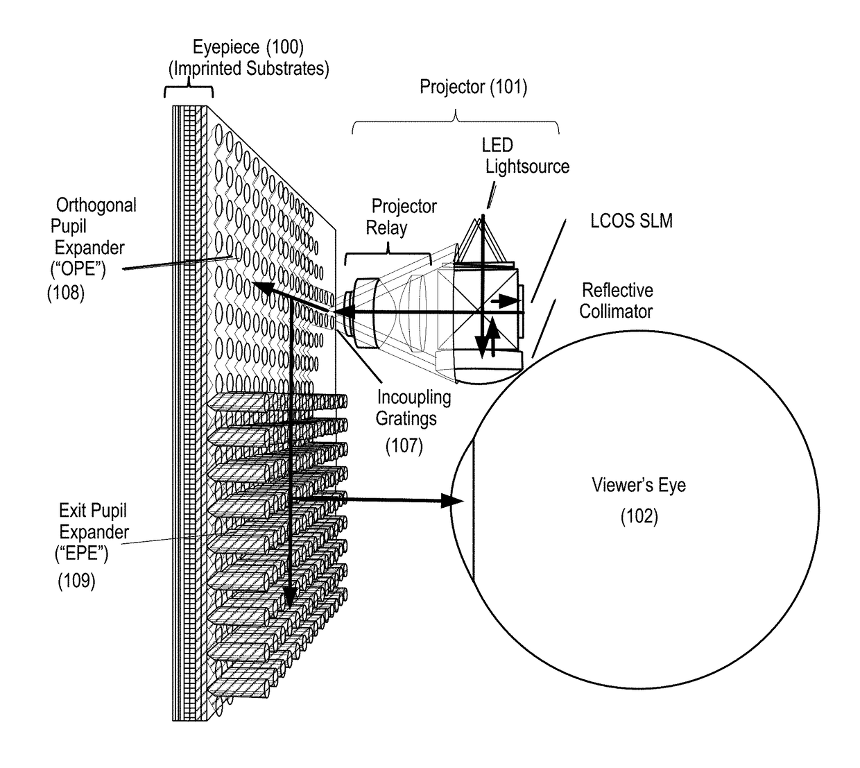
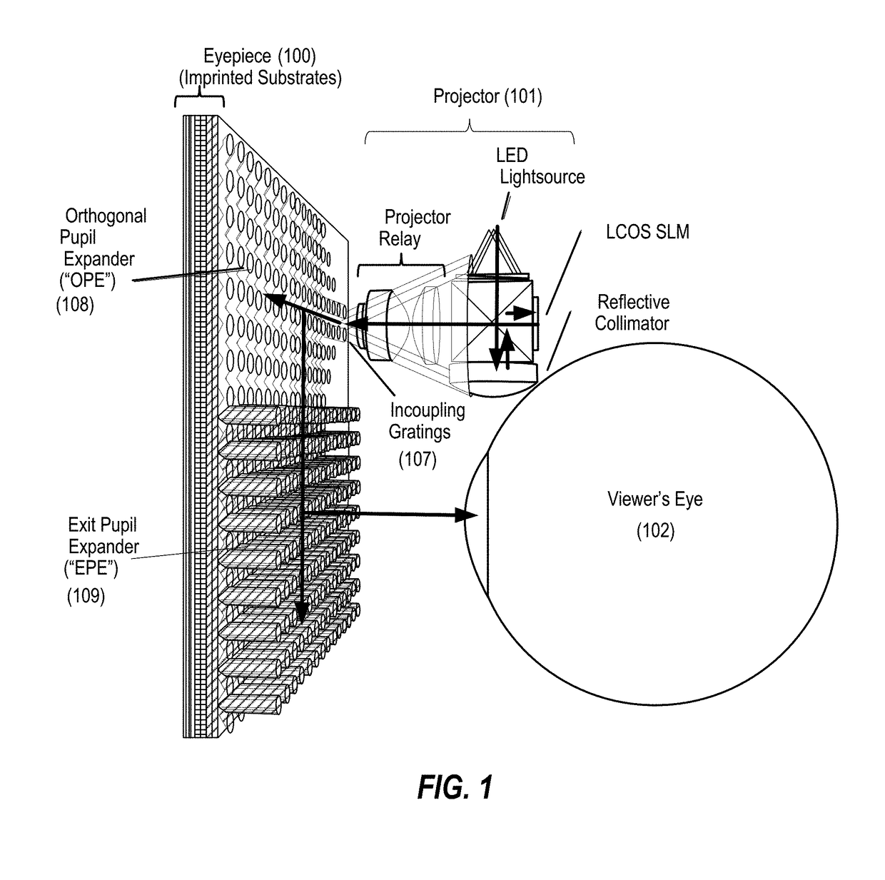
[0064]FIG. 1 schematically illustrates light paths in a viewing optics assembly (VOA) that may be used to present a digital or virtual image to a viewer, according to some embodiments. The VOA includes a projector 101 and an eyepiece 100 that may be worn around a viewer's eye 102. In some embodiments, the projector 101 may include a group of red LEDs, a group of green LEDs, and a group of blue LEDs. For example, the projector 101 may include two red LEDs, two green LEDs, and two blue LEDs. The eyepiece 10...


PUM


Abstract

An eyepiece unit with optical filters includes a set of waveguide layers including a first waveguide layer and a second waveguide layer. The first waveguide layer is disposed in a first lateral plane and includes a first incoupling diffractive element disposed at a first lateral position, a first waveguide, and a first outcoupling diffractive element. The second waveguide layer is disposed in a second lateral plane adjacent to the first lateral plane and includes a second incoupling diffractive element disposed at a second lateral position, a second waveguide, and a second outcoupling diffractive element. The eyepiece unit also includes a set of optical filters including a first optical filter positioned at the first lateral position and operable to attenuate light outside a first spectral band and a second optical filter positioned at the second lateral position and operable to attenuate light outside a second spectral band.

Description

CROSS REFERENCE TO RELATED APPLICATIONS[0001]This application claims priority to U.S. Provisional Patent Application No. 62 / 459,559, filed on Feb. 15, 2017, entitled “METHOD AND SYSTEM FOR MULTI-PUPIL DISPLAY SYSTEM WITH LIQUID CRYSTAL SHUTTER,” U.S. Provisional Patent Application No. 62 / 459,964, filed on Feb. 16, 2017, entitled “METHOD AND SYSTEM FOR REDUCTION OF OPTICAL ARTIFACTS IN AUGMENTED REALITY DEVICES,” and U.S. Provisional Patent Application No. 62 / 592,607, filed on Nov. 30, 2017, entitled “PROJECTOR ARCHITECTURE INCORPORATING ARTIFACT MITIGATION,” the disclosures of which are hereby incorporated by reference in their entirety for all purposes.BACKGROUND OF THE INVENTION[0002]Modern computing and display technologies have facilitated the development of systems for so-called “virtual reality” or “augmented reality” experiences, wherein digitally produced images or portions thereof are presented in a wearable device to a user in a manner wherein they seem to be, or may be pe...

Claims


Application Information

Patent Timeline
IPC IPC(8): G02B27/00F21V8/00G03B21/20G03B21/00G02B27/28
CPCG02B27/0018G02B6/0076G02B6/0038G02B6/0026G02B6/0016G03B21/2073G03B21/2033G03B21/005G02B27/283G03B21/208G02B27/0081G03B21/2013G03B21/142G03B21/14G02B27/42G02B27/0101G02B25/001G02B6/00G02B6/126G02B6/02052G02B6/29316G02B27/4233G02B5/1814G02B5/30G02B2027/011G02B5/20G02B2027/012
Inventor SCHUCK, III, MILLER HARRYCURTIS, KEVIN RICHARDCHENG, HUI-CHUANSISSOM, BRADLEY JAYGRECO, PAUL M.WELCH, WILLIAM HUDSONBROWY, ERIC C.
Owner MAGIC LEAP
Features
  • Generate Ideas
  • Intellectual Property
  • Life Sciences
  • Materials
  • Tech Scout
  • Unparalleled Data Quality
  • Higher Quality Content
  • 60% Fewer Hallucinations
Learn More