
Process chamber shielding system and method

a shielding system and process chamber technology, applied in the direction of vacuum evaporation coating, chemical vapor deposition coating, coating, etc., can solve the problems of reducing the contact area and reducing the bonding strength between the coating, so as to improve the reception and retention of excess material

Inactive Publication Date: 2018-08-23
SWISS RANKS PTE LTD
View PDF2 Cites 0 Cited by
  • Summary
  • Abstract
  • Description
  • Claims
  • Application Information

AI Technical Summary

Benefits of technology

The patent is about a removable coating for protecting process chamber components from excess material. The coating includes a sheet with a bonding surface for bonding to the process chamber component and a deposition surface for receiving excess material. The deposition surface is treated to improve the reception and retention of excess material, such as by plasma coating or spray coating material onto the sheet. This treatment includes a bonding texture in the bonding surface, reducing the contact area and heat transfer rate between the coating and the process chamber component. The method also includes steps to prepare the bonding surface and deposition surface for bonding and to treat them for better bonding or to improve the capture and retention of excess material. The removable coating makes it easier and faster to clean and put the process chamber back in service, as compared to traditional surface treatments like bead blasting or aluminum arc spraying. Additionally, the patent mentions the option of replacing the removable coating with a replacement removable coating of the same or similar nature, quickly and easily.

Problems solved by technology

The reduced contact area may reduce a bonding strength between the coating and the process chamber component.

Method used


Image

  • Process chamber shielding system and method
  • Process chamber shielding system and method
  • Process chamber shielding system and method

Examples


Embodiment Construction

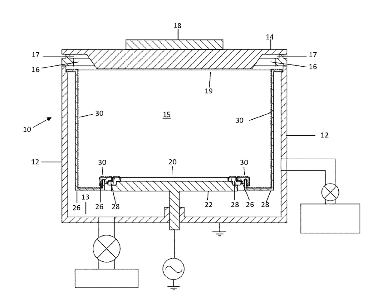
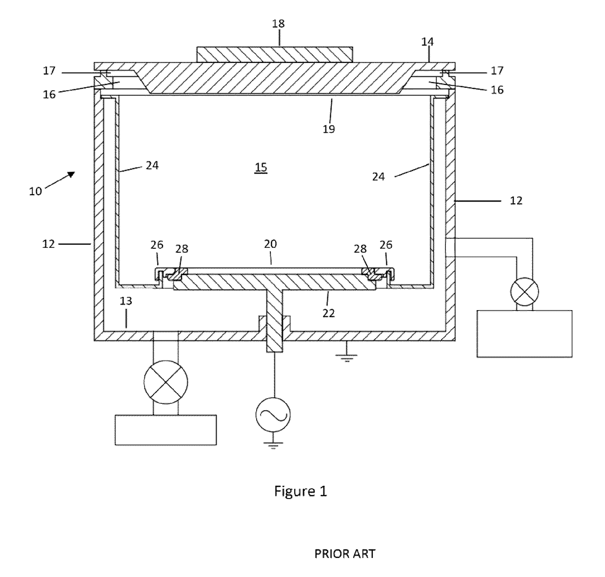
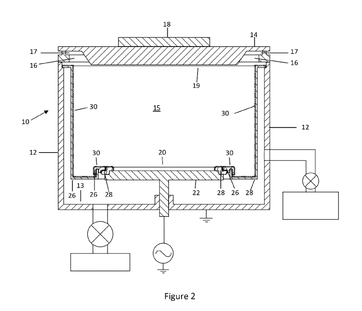
[0041]Referring to FIG. 1, a cross-section of an exemplar prior art process chamber 10 is illustrated. The process chamber 10 includes a chamber body defined by chamber walls 12, base 13 and cover 14. The chamber body defines a chamber cavity 15 in which the process is contained. The chamber walls 12 and base 13 are commonly constructed in fixed arrangement to one another with the cover 14 being removable. Typically, a sealing ring 16 and sealing gasket 17 are provided to assist with securing the cover 14 in sealing engagement with the walls 12. A magnet 18 is provided above the cover 14 to work in cooperation with a target 19 located on the inside of the cover 14 to generate material to be deposited on a substrate.

[0042]Below the target 19 a pedestal 22 is provided for supporting the wafer 20 to be coated in the process chamber 10. Typically, a heater is located beneath, or within, the pedestal 22 for heating the substrate (wafer 20) and the chamber cavity 15. As illustrated in FIG...


PUM

PropertyMeasurementUnit
thickaaaaaaaaaa
thickaaaaaaaaaa
thicknessaaaaaaaaaa

Abstract

A removable coating for protecting process chamber components from excess material resulting from operation of a process chamber. The removable coating including a sheet. A bonding surface of the sheet to be releasably bonded to a process chamber component to be protected. A deposition surface of the coating selected to receive and retain the excess material. In an aspect, the coating may further include a deposition layer bonded to a sheet surface in opposition to the bonding surface. The deposition layer providing the deposition surface. In some aspects the deposition surface may be provided of a different material from the process chamber component. In some aspects, and method and system are provided for protecting process chamber components.

Description

CROSS-REFERENCE TO RELATED APPLICATION[0001]This application claims priority to U.S. Provisional Patent Application Ser. No. 62 / 208,613 filed on Aug. 22, 2015, the contents of which are incorporated entirely herein by reference.FIELD OF THE INVENTION[0002]The following relates generally to process chambers for thin film deposition in semiconductor fabrication, and more particularly an improved system and method for shielding the various components of a process chamber.BACKGROUND OF THE INVENTION[0003]Physical vapour deposition (PVD), otherwise known as sputtering, is a process by which a film may be deposited on a substrate during the fabrication of semiconductors. PVD is a plasma process conducted within a vacuum process chamber, and involves bombarding a target with ions to cause the target to eject atoms. The ejected atoms build up as a deposited film on an intended semiconductor substrate being supported within the process chamber.[0004]Chemical Vapour Deposition (CVD) is a proc...

Claims


Application Information

Patent Timeline
Patent Type & Authority Applications(United States)
IPC IPC(8): C23C14/56C23C16/44B05D1/32
CPCC23C14/564C23C16/4401B05D1/322C23C16/4404
Inventor MONTES, ROMMELTHIRU, RAJANTHIRUN, RAVI
Owner SWISS RANKS PTE LTD
Learn More