Refrigeration apparatus for containers

Active Publication Date: 2018-08-30
DAIKIN IND LTD
View PDF92 Cites 22 Cited by
  • Summary
  • Abstract
  • Description
  • Claims
  • Application Information

AI Technical Summary

Benefits of technology

[0028]According to the first and second aspects of the invention, the external end of the exhaust passage (46a) is open on the suction side of the external fan (25) in the exterior storage space (51). Thus, rotation of the external fan (25) allows the pressure on the suction side of the external fan (25), around which the external end of the exhaust passage (46a) opens, to become lower than the pressure on the blowout side of the internal fan (26) around which the internal end of the exhaust passage (46a) opens. Thus, even if the pressure in the container (11) is lower than the outside pressure, the external fan (25) allows the pressure in a space in which the internal end of the exhaust passage (46a) opens to become higher than the pressure in a space in which the external end of the exhaust passage (46a) opens. Due to the pressure difference between the ends of the exhaust passage (46a) caused by the rotation of the external fan (25), the air in the internal storage space (S2) communicating with the interior of the container (inside air) can be smoothly exhausted out of the container. Therefore, the composition of the air in the container (oxygen concentration and carbon dioxide concentration) may quickly and accurately be controlled to a desired composition.
[0029]Further, according to the third aspect, the external portion of the exhaust tube (46a) is at least partially disposed in the second space (S12) of the exterior storage space (S1) downstream of the condenser (22) in the direction of the flow of the outside air. With the exhaust passage (46a) thus arranged, the air flowing from the interior to exterior of the container (11) via the exhaust passage (46a) is heated in the external portion of the exhaust passage (46a) by the outside air that has been heated by the refrigerant when passing through the condenser (22). Thus, even if the outside air temperature is remarkably low, condensation of moisture in the air flowing in the external portion of the exhaust pass

Problems solved by technology

Thus, if the carbon dioxide concentration in the air in the container exceeds an upper l

Method used


Image

  • Refrigeration apparatus for containers
  • Refrigeration apparatus for containers
  • Refrigeration apparatus for containers

Examples


first embodiment

Advantages of First Embodiment

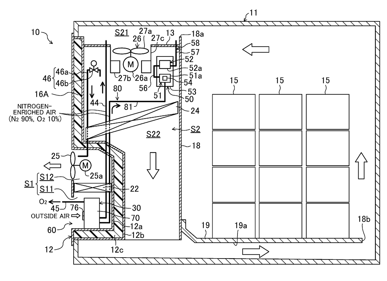
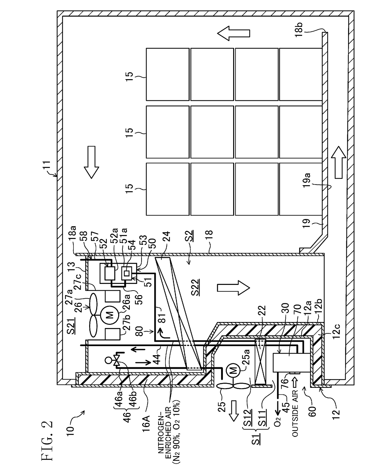
[0169]As can be seen in the foregoing, according to the first embodiment, the exhaust tube (exhaust passage) (46a) is open on the suction side of the external fan (25) in the external storage space (S1). Thus, rotation of the external fan (25) allows the pressure on the suction side of the external fan (25), around which the external end of the exhaust tube (46a) opens, to become lower than the pressure on the blowout side of the internal fans (26) around which the internal end of the exhaust tube (46a) opens. Thus, even if the pressure in the container (11) is lower than the outside pressure, the external fan (25) allows the pressure in a space in which the internal end of the exhaust tube (46a) opens to become higher than the pressure in a space in which the external end of the exhaust tube (46a) opens. Due to the pressure difference between the ends of the exhaust tube (46a) caused by the rotation of the external fan (25), the air in the internal sto...

second embodiment

Advantages of Second Embodiment

[0177]As can be seen, according to the second embodiment, the exhaust valve (46b) is automatically opened or closed based on the difference between the pressure in the container (11) and the pressure in the second space (S12) without being controlled by the controller (55), just like in the first embodiment. Thus, the pressure in the container (11) is stabilized at a higher level than the pressure in the exterior second space (S12) only by the predetermined pressure value. As a result, the gas supply operation and the outside air introducing operation are stably performed. Thus, the composition of the air in the container (11) (oxygen concentration and carbon dioxide concentration) may be controlled easily and accurately.

third embodiment

[0178]As shown in FIG. 11, a third embodiment is a modified version of the first and second embodiments, in which the positional relationship among the condenser (22), the external fan (25), the electrical component box (17), and the inverter box (29) in the external storage space (51) is modified.

[0179]Specifically, according to the third embodiment, the condenser (22), which has extended linearly in a horizontal direction in the first and second embodiments, has three heat exchange surfaces (22a, 22b, 22c) arranged in the shape of U. The condenser (22) is placed above the center of the external storage space (S1) with the heat exchange surface (22a) serving as a top surface, the heat exchange surface (22b) as a right side surface, and the heat exchange surface (22c) as a bottom surface. Further, the external fan (25) that has been arranged above the condenser (22) in the first and second embodiments is placed inside the U-shaped condenser (22). Likewise, the electrical component b...


PUM


Abstract

A container refrigeration apparatus includes: a casing which forms an external storage space communicating with the exterior of the container and an internal storage space communicating with the interior of the container; a refrigerant circuit; an external fan; an internal fan; and an inside air control system including an exhaust passage which allows a space on a blowout side of the internal fan in the internal storage space to communicate with the external storage space, and controls composition of the inside air in the container. An external end of the exhaust passage is open on a suction side of the external fan in the external storage space.

Description

TECHNICAL FIELD[0001]The present invention relates to a container refrigeration apparatus which cools air in a container and controls the composition of the air in the container.BACKGROUND ART[0002]Container refrigeration apparatuses including a refrigerant circuit performing a refrigeration cycle have been used to cool air in a container for use in, e.g., marine transportation (see, e.g., Patent Document 1). The container is loaded with plants such as bananas and avocados, for example. Plants perform respiration by absorbing oxygen in the air and releasing carbon dioxide even after they have been harvested. The plants lose their nourishment and moisture as they respire. Thus, if the respiration rate of the plants increases, the degree of freshness of the plants decreases significantly. Thus, it is recommended that the oxygen concentration in the container be lowered not to cause respiratory problems.[0003]Patent Document 1 discloses an internal environment control system which sepa...

Claims


Application Information

Patent Timeline
IPC IPC(8): F25D17/04F25D11/00F25D21/14F25D23/00A23B7/148A23B7/04
CPCF25D17/042F25D11/003F25D21/14F25D23/003A23B7/148A23B7/0425F25D2317/04A23V2002/00B65D88/745F25D17/045F25D17/06
Inventor KAMEI, NORITAKAOZATO, ATSUSHIHIRATA, WATARU
Owner DAIKIN IND LTD
Why Eureka
Try Eureka