Capacitive transducer and acoustic sensor

a capacitive transducer and acoustic sensor technology, applied in the field of capacitive transducers and acoustic sensors, can solve the problems of inability to adapt to digital and miniaturization, inability to digitize and miniaturize, and deformation of thin vibration electrode films, etc., to achieve good frequency characteristics, improve performance, and improve reliability

Active Publication Date: 2018-08-30
MMI SEMICON CO LTD
View PDF2 Cites 2 Cited by
  • Summary
  • Abstract
  • Description
  • Claims
  • Application Information

AI Technical Summary

Benefits of technology

[0024]The capacitive transducer according to one or more of the above aspects can maintain good frequency characteristics during pressure detection, and prevents the vibration electrode film from deforming

Problems solved by technology

However, ECMs are susceptive to heat and are less suited to digitization and miniaturization than microphones incorporating capacitive transducers fabricated using the micro electro mechanical systems (MEMS) technology (hereafter, MEMS microphones).
The thin vibration electrode film may deform greatly and break under an excessively high pressure.
The capacitive transducer may have this disadvantage when, for example, receiving an air blow in its mounting process or when the capacitive transducer falls, in addition to when receiving a large sound pressure.
However, this may degrade the frequency characteristics of the capacitive transducer, or may reduce the sensitivity within a low-frequency sound range.
This causes the area of air passage to either remain constant or decrease, causing difficulties in

Method used


Image

  • Capacitive transducer and acoustic sensor
  • Capacitive transducer and acoustic sensor
  • Capacitive transducer and acoustic sensor

Examples


first embodiment

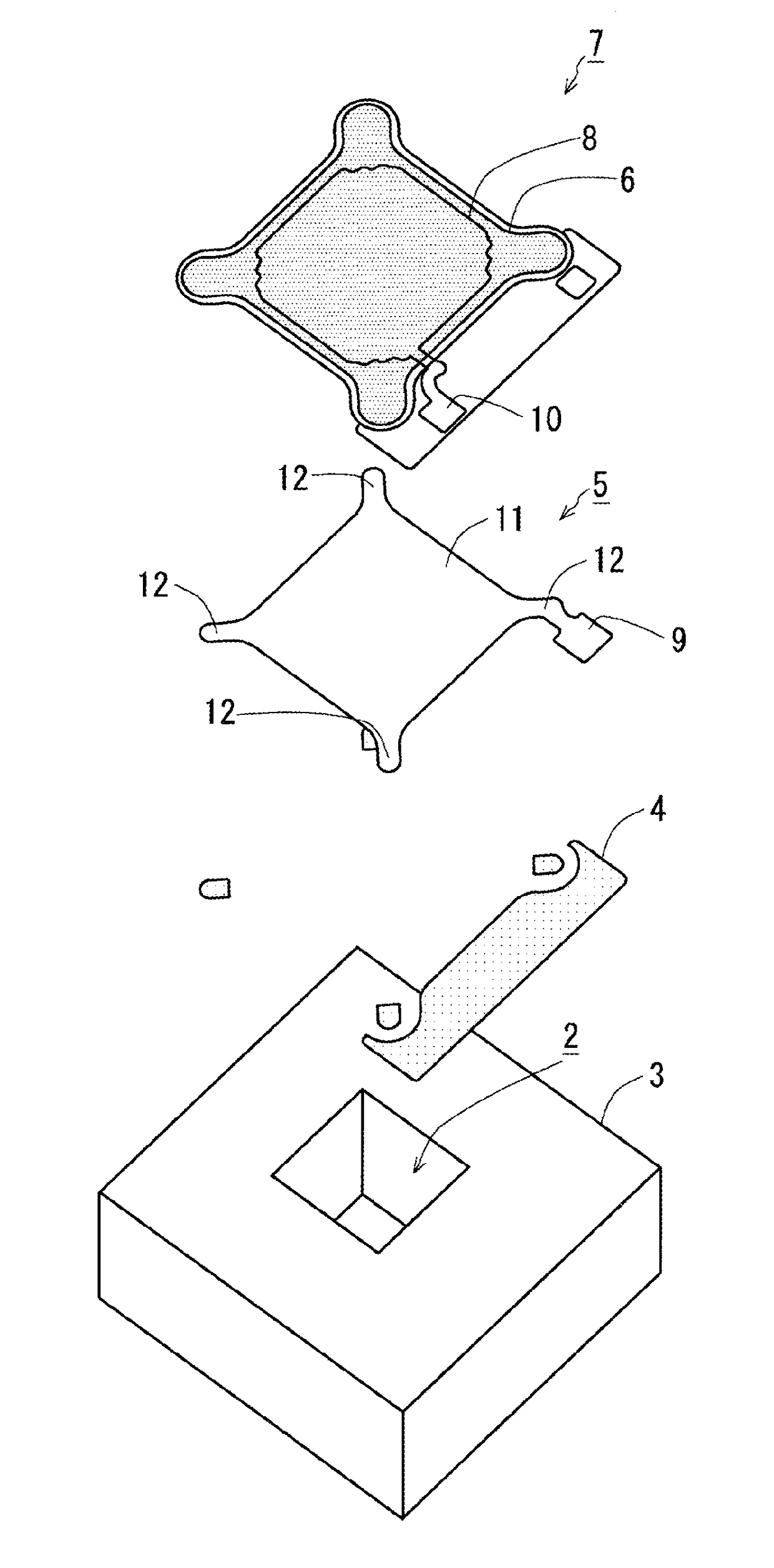
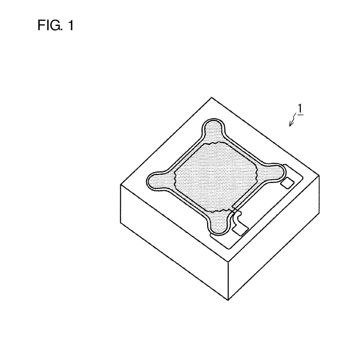
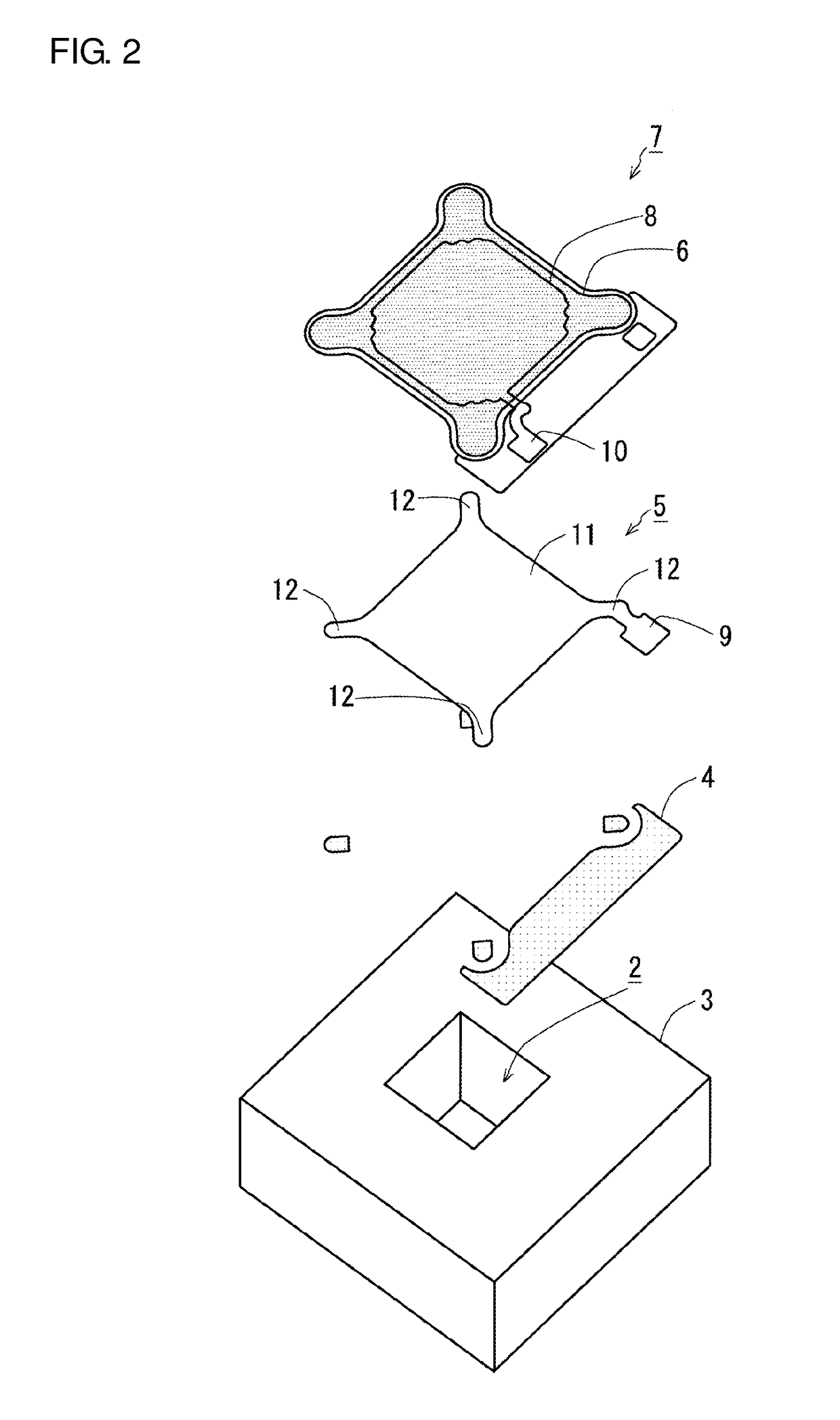
[0045]Embodiments of the present invention will now be described with reference to the drawings. The embodiments described below are mere examples of this invention and should not be construed as limiting the technical scope of the invention. Although the present invention is applicable to any electrostatic transducer, an electrostatic transducer used as an acoustic sensor will be described. However, a voice transducer according to the embodiments of the present invention may be used as any non-acoustic sensor for detecting the displacement of a vibration electrode film. For example, the transducer may be used as a pressure sensor, an acceleration sensor, or an inertial sensor. In addition, the transducer may be used as a non-sensor device such as a speaker for converting an electrical signal into a displacement. The components including a back plate, a vibration electrode film, a back chamber, and a substrate may be in any arrangement that provides the same functions as produced by...

second embodiment

[0079]A second embodiment of the present invention will now be described. In the present embodiment, a sound hole is formed in a substantially columnar protrusion integral with a back plate. The sound hole includes the side surface of the protrusion in the horizontal direction, and extends in the protrusion halfway in the vertical direction. This sound hole increases the area of the pressure relief channel adjacent to the base of the protrusion.

[0080]FIG. 14 is a cross-sectional view showing a protrusion 77b formed on a back plate 77 and a pressure relief hole 75b formed in a vibration electrode film 75 according to the present embodiment. The protrusion 77b in the present embodiment, which is substantially columnar, is formed with the sound hole in the back plate 77 by etching. More specifically, a cavity 77c is formed to include the side surface of the columnar protrusion 77b in the horizontal direction and extend in the columnar protrusion 77b halfway in the vertical direction, w...

third embodiment

[0083]A third embodiment of the present invention will now be described. In the present embodiment, a tapered protrusion that decreases its diameter from a back plate toward the distal end has an opening in a part of the side surface adjacent to the back plate, and a cavity extending through the opening and the top of the back plate.

[0084]FIGS. 15A and 15B show the function of a known tapered protrusion that decreases its diameter from a back plate toward the distal end, and the function of such a protrusion having an opening in a part of the side surface adjacent to the back plate and a cavity extending through the opening and the top of the back plate.

[0085]FIG. 15A shows a typical tapered protrusion. FIG. 15B shows a tapered protrusion having such an opening and a cavity extending through the opening and the top of the back plate. In the structure having a typical tapered protrusion 87b as shown in FIG. 15A, a vibration electrode film 85 deforms toward the back plate 87 under an ...


PUM


Abstract

A capacitive transducer includes a substrate having an opening in a surface thereof, a back plate facing the opening in the substrate, a vibration electrode film facing the back plate across a space, the vibration electrode film being deformable to have a deformation converted into a change in capacitance between the vibration electrode film and the back plate, the vibration electrode film having a through-hole as a pressure relief hole, and a protrusion integral with and formed from the same member as the back plate, the protrusion being placeable in the pressure relief hole before the vibration electrode film deforms. The protrusion and the pressure relief hole have a gap therebetween defining an airflow channel as a pressure relief channel.

Description

BACKGROUNDField[0001]The disclosure relates to a capacitive transducer and an acoustic sensor including the capacitive transducer. The present invention particularly relates to a capacitive transducer with a capacitor structure including a vibration electrode film with the MEMS technology and a back plate, and to an acoustic sensor including the capacitive transducer.Related Art[0002]Small microphones known in the art may incorporate acoustic sensors called electret condenser microphones (ECMs). However, ECMs are susceptive to heat and are less suited to digitization and miniaturization than microphones incorporating capacitive transducers fabricated using the micro electro mechanical systems (MEMS) technology (hereafter, MEMS microphones). Thus, MEMS microphones have been increasingly used (refer to, for example, Patent Literature 1).[0003]A capacitive transducer fabricated using the MEMS technology may include a vibration electrode film that vibrates under pressure and a back plat...

Claims


Application Information

Patent Timeline
IPC IPC(8): H04R19/04
CPCH04R19/04B81B3/00H04R19/005H01L29/84B81B3/0002B81B3/001B81B3/0056
Inventor KASAI, TAKASHIMOMOTANI, KOJITERASAKA, MARIKO
Owner MMI SEMICON CO LTD
Why Eureka
Try Eureka