
Simultaneous ct-mri image reconstruction

a ctmri image and simulation technology, applied in the field of simulation of ctmri image reconstruction, can solve the problems of insufficient single modality to depict the complex dynamics of mammalian physiology and pathology, poor anatomic localization of radionuclide uptake, and long scanning time, so as to improve ct and mm reconstruction and improve ct and mri image quality

Active Publication Date: 2018-09-06
RENESSELAER POLYTECHNIC INST
View PDF0 Cites 20 Cited by
  • Summary
  • Abstract
  • Description
  • Claims
  • Application Information

AI Technical Summary

Benefits of technology

This patent describes a new and effective way to get simultaneous computed tomography (CT) and magnetic resonance imaging (MRI) images. The invention combines two techniques, called structural coupling and compressive sensing, to improve the quality of both types of images. By using a bidirectional image estimation method, the CT and MRI data can be connected to each other, resulting in better quality images than would be possible with separate reconstruction.

Problems solved by technology

However, each individual imaging modality has its own contrast mechanism with strengths and weaknesses, and imaging protocols depend on many interrelated factors.
Prior to the availability of hybrid PET-CT, separate CT and PET scans were performed often with longer scanning time and poor anatomic localization of radionuclide uptake, due to post-acquisition image fusion errors.
However, no single modality is sufficient to depict the complex dynamics of mammalian physiology and pathology.
Even with current multi-modality imaging, though, limitations exist, including reconstruction techniques that are inefficient and / or inaccurate.

Method used


Image

  • Simultaneous ct-mri image reconstruction
  • Simultaneous ct-mri image reconstruction
  • Simultaneous ct-mri image reconstruction

Examples


embodiment 1

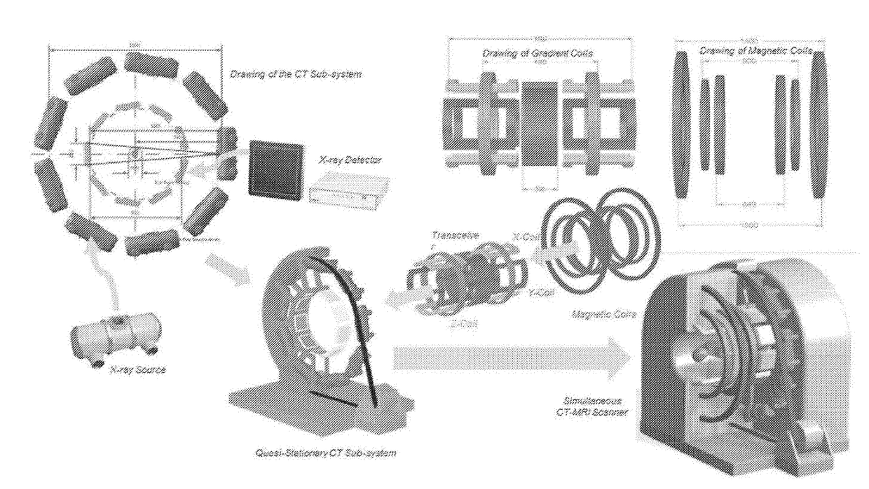
[0146]A system for simultaneous computed tomography (CT)-magnetic resonance imaging (MRI), the system comprising:

[0147]a CT subsystem for obtaining CT data;

[0148]an MRI subsystem for obtaining MRI data;

[0149]at least one processor; and

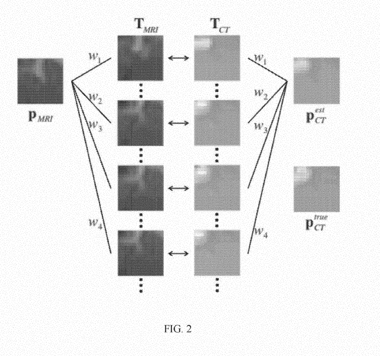
[0150]a machine-readable medium, in operable communication with the CT subsystem, the MRI subsystem, and the at least one processor, having machine-executable instructions stored thereon that, when executed by the at least one processor, perform a method of reconstructing CT and MRI images, the method comprising:[0151]i) reconstructing a CT image uCT from the CT data;[0152]ii) reconstructing an MRI image uMRI from the MRI data;[0153]iii) setting an iteration step k=0;[0154]iv) transforming a CT-MRI dataset TCT-MRI by the uCT and uMRI;[0155]v) estimating the corresponded CT-MRI image

uestCTanduestMRI

according to uCT and uMRI aided by the CT-MRI dataset TCT-MRI;[0156]vi) reconstructing the CT image uCT with

uestCT

and the CT data;[0157]vii) reconstructing t...

embodiment 2

[0160]The system according to embodiment 1, wherein reconstructing a CT image uCT from the CT data comprises using the following equation:

minuCTuCTTVs.t.MuCT=f,

where M is a system matrix, f is the (line integral) CT data (after preprocessing), and ∥⋅∥TV represents a total variation (TV) transformation.

embodiment 3

[0161]The system according to any of embodiments 1-2, wherein reconstructing an MRI image uMRI from the MRI data comprises using the following equation:

minuMRIuMRITVs.t.RFuMRI=g,

where F denotes the Fourier transform, R is a sampling mask in the k-space, g is the MRI data, and ∥⋅∥TV represents a total variation (TV) transformation.


PUM


Abstract

Novel and advantageous systems and method for obtaining and / or reconstructing simultaneous computed tomography (CT)-magnetic resonance imaging (MRI) images are provided. Structural coupling (SC) and compressive sensing (CS) techniques can be combined to unify and improve CT and MRI reconstruction. A bidirectional image estimation method can be used to connect images from different modalities, with CT and MM data serving as prior knowledge to each other to produce better CT and MRI image quality than would be realized with individual reconstruction.

Description

CROSS-REFERENCE TO A RELATED APPLICATION[0001]This application is a national stage filing of International Patent Application No. PCT / US2016 / 051755, filed Sep. 14, 2016, which claims the benefit of U.S. Provisional Application Ser. No. 62 / 218,239, filed Sep. 14, 2015, which are incorporated herein by reference in their entirety.BACKGROUND[0002]According to the National Center for Health Statistics, heart and oncologic diseases are the top two causes of mortality in the United States. Considerable strides have been made in imaging of these maladies with technologic innovations in computed tomography (CT), magnetic resonance imaging (MRI), single photon emission computed tomography / positron emission tomography (SPECT / PET), ultrasound, and optical imaging including optical coherence tomography (OCT) and fluorescence imaging. These imaging modalities are routinely used worldwide, producing critical tomographic information of the human body and enabling evaluation of not only anatomical ...

Claims


Application Information

Patent Timeline
IPC IPC(8): A61B6/00A61B5/00A61B5/055A61B6/03G06T11/00G01R33/48G01R33/56G01R33/3815
CPCA61B6/5247A61B5/0035A61B5/055A61B6/035A61B6/4417G06T11/006G01R33/4812G01R33/5608G01R33/3815G06T2211/424A61B6/032A61B6/5205
Inventor WANG, GEXI, YANCONG, WENXIANGZHAO, JUN
Owner RENESSELAER POLYTECHNIC INST
Learn More