Fingertip identification for gesture control

a fingertip and gesture control technology, applied in the field of fingertip identification, can solve the problems of affecting the stability of the skeletal approach, affecting the interaction, and affecting the accuracy of the fingertip tracking,

Active Publication Date: 2018-09-13
UMAJIN
View PDF0 Cites 4 Cited by
  • Summary
  • Abstract
  • Description
  • Claims
  • Application Information

AI Technical Summary

Benefits of technology

[0020]The method may be one wherein the processor identifies fingers and determines respective angles in two dimensional space of the identified fingers. An advantage is that input from the pointing direction of fingers is therefore readily obtained.
[0021]The method m

Problems solved by technology

Existing skeletal tracking solutions have problems where the final inverse kinematic phase, which attempts to rectify the skeleton, will almost always reposition joints including the final position of the fingertips—as a result the fingertips are almost always pushed off centre and often outside of the hand silhouette.
This causes a lot of inaccuracy and jitter between frames for the fingertip tracking.
This seriously undermines the stability of the skeletal approach, making it very difficult to use for interaction.
Users do not get clear feedback why the hand tracking is failing as they are still clearly holding their hand up in front of the camera frustum—they do not understand that there is only a partial match in the hand tracking process.
Accessibility to the bottom of the screen is very unreliable with the skeletal approach, because, when approaching the bottom of the screen, approximately the bottom half of the hand or hands may not be in view. FIG. 2 shows an example of a poor result in attempted finger tracking, in which two hands are only partially in view when approaching the bottom

Method used


Image

  • Fingertip identification for gesture control
  • Fingertip identification for gesture control
  • Fingertip identification for gesture control

Examples


Embodiment Construction
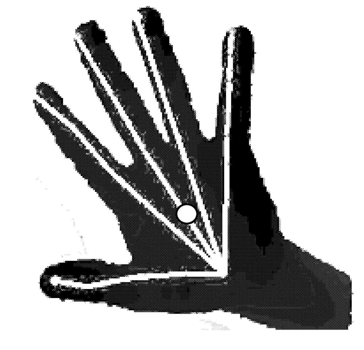
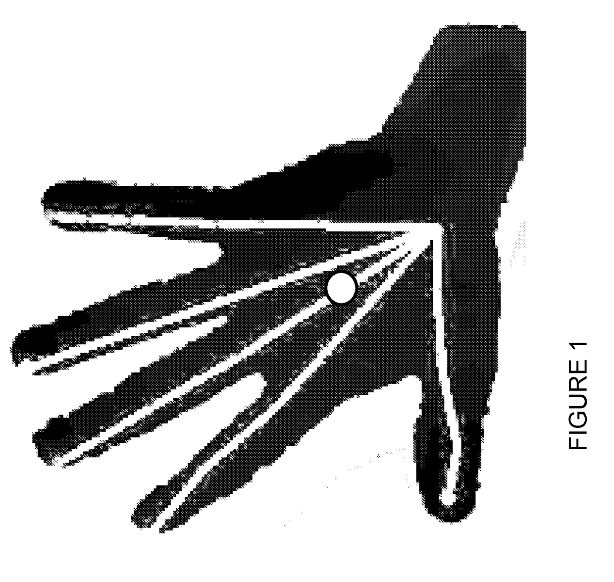
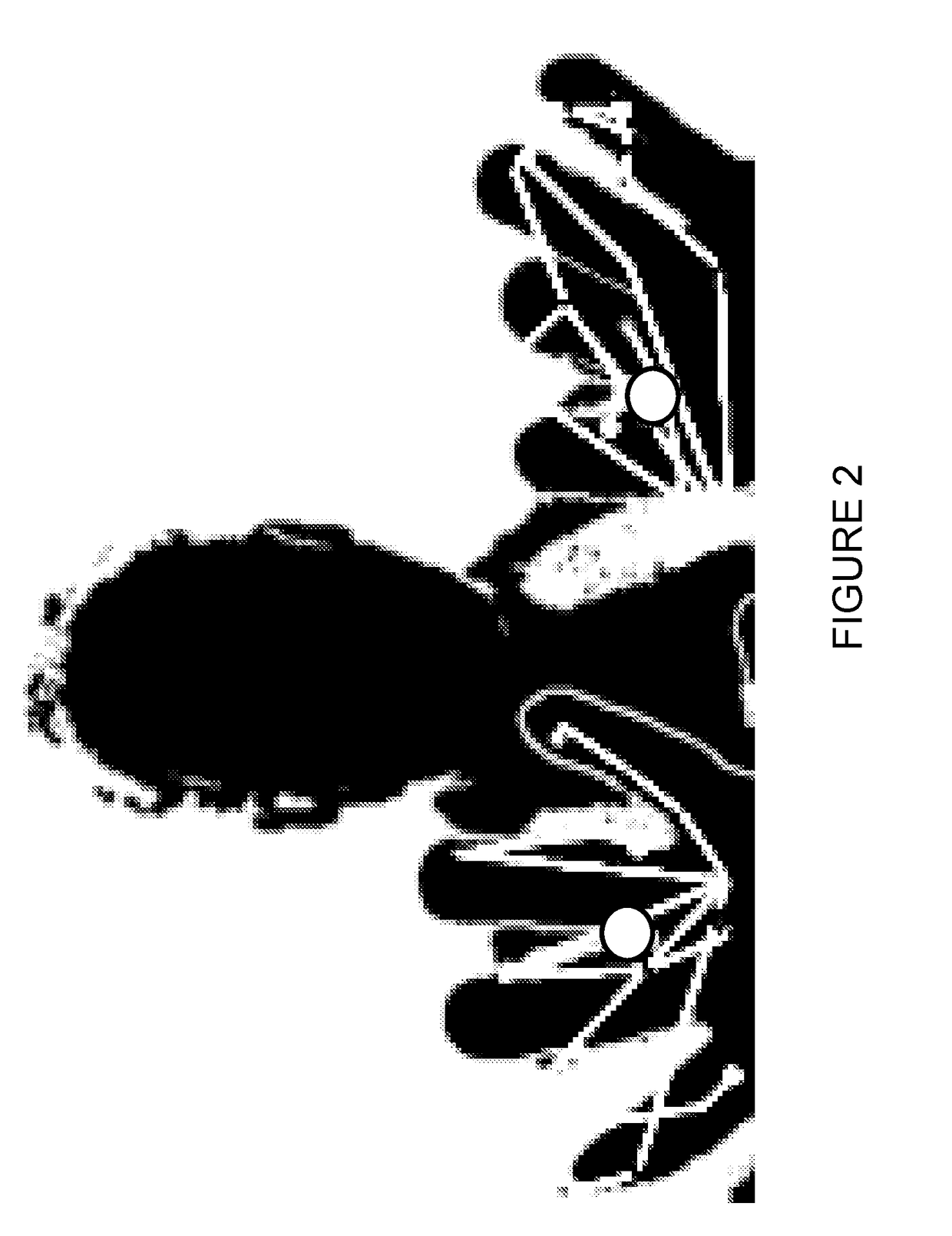
[0069]Ghost Hands

[0070]‘Ghost hands’ is a user interface paradigm for using 2D and 3D user interfaces with fingertips. The fingertips are scanned or detected using a 3D or depth sensing camera system such as an Intel Real Sense or Microsoft Kinect. A 3D or depth sensing camera system typically includes a conventional camera, an infrared laser projector, an infrared camera, and a microphone array. The infrared projector projects a grid onto the scene (in infrared light which is invisible to human eyes) and the infrared camera records it to compute depth information. A stereoscopic camera system is another example of a 3D or depth sensing camera system.

[0071]The Ghost Hands solution is applicable, for example, to desktop, Augmented Reality, Virtual Reality and Tabletop Mixed Reality scenarios. For example, where the 3D or depth sensing camera is mounted in the bezel of a laptop or tablet—where a 3D or depth sensing camera is mounted onto a wearable device, such as a stereoscopic heads...


PUM


Abstract

A computer implemented method of fingertip centroid identification in real-time, implemented on a computer system comprising a processor, memory, and a camera system. The processor receives image data from the camera system; runs a first kernel comprising a set of concentric closed shapes over image data to identify an occupancy pattern in which internal closed shapes are at least nearly fully occupied, and in which a subsequent closed shape has at least a relatively low occupancy level, so as to identify one or more fingertips in the image data; for each identified fingertip, runs a second kernel over the identified one or more fingertips to establish a best fit closed shape which covers each identified fingertip; calculates a centroid for each best fit closed shape which corresponds to an identified fingertip; and stores in the memory the calculated centroids for the identified one or more fingertips.

Description

BACKGROUND OF THE INVENTION1. Field of the Invention[0001]The field of the invention relates to methods of fingertip identification, and to related systems and computer program products.2. Technical Background[0002]One problem with several conventional 3D or depth sensing camera systems is that they find it difficult to accurately detect and track the movements of fingertips, making it difficult to mimic accurately 2D touch screen or touch pad interactions, such as tapping, dragging, selecting, scrolling, zooming etc.3. Discussion of Related Art[0003]Inverse kinematics refers to the use of the kinematics equations of e.g. an animated character to determine the joint parameters that provide a desired configuration of the animated character. Specification of the movement of the animated character so that its configuration achieves a desired motion as a function of time is known as motion planning. Inverse kinematics transforms the motion plan into joint actuation trajectories for the ...

Claims


Application Information

Patent Timeline
IPC IPC(8): G06K9/00G06F3/01H04N13/204H04N5/33G06T7/13G06T7/136G06T7/155G06T1/20
CPCG06K9/00006G06F3/017H04N13/204H04N5/33G06T7/13G06T7/136G06T7/155G06T1/20G06T2207/10028G06T2207/20132G06F3/011G06F3/005G06F3/0425G06V40/12
Inventor BREBNER, DAVIDROUNTREE, RICHARD
Owner UMAJIN
Why Eureka
Try Eureka