Nitrocellulose extrusion for porous film strips

a technology of nitrocellulose and porous film, which is applied in the field of methods and systems for making nitrocellulose polymer films, can solve the problems of cumbersome production, laborious process, and cumbersome lfa devices of et al. and others, and achieves the effects of improving field stability, high sensitivity, and rapid diagnosis

Inactive Publication Date: 2018-09-20
GRACE BIO-LABS
View PDF0 Cites 13 Cited by
  • Summary
  • Abstract
  • Description
  • Claims
  • Application Information

AI Technical Summary

Benefits of technology

[0020]The use of the nitrocellulose-based strips produced with a plurality of pores of a uniform size or sizes without the need for inefficient processing and assembly steps to carry microarrays of binding ligands allows for the creation of reproducible products that can be used with an image acquisition system with high sensitivity and rapid diagnosis. In some aspects, the captured biomolecules may be tagged with a fluorescent label. While any fluorescent label may be used, in some aspects the fluorescent labels may comprise organic fluorophores (e.g., dyes). By using organic fluorophores to label the biomolecules, field stability of the fluorescent label may be increased while costs are decreased and the sensitivity and resolution of the images captured by the image acquisition system are maintained, allowing for improved accuracy in the diagnosis of infectious disease.
[0021]In one example, the imaging issues described above may be addressed by an optical assembly that may be user alone or as part of a larger microarray assembly. The optical assembly may comprise one or more light sources such as lasers configured to illuminate ligands bound to a substrate. In some examples, the ligands may be fluorescently or colorimetrically labeled. The light sources may emit the same or different wavelengths of light and may be placed parallel to one another and perpendicular to the axis of the substrate to minimize the size needed for the device. While the light sources may be positioned parallel to one another, the light emitted from the one or more light sources may be angled to engage with the fluorescently labeled ligands bound to the substrate with or without the use of mirrors. The optical assembly may additionally include a camera positioned to capture light emitted from the fluorescently labeled ligands bound to the substrate. The camera may be positioned parallel to the light sources and centrally located between two or more light sources such that the camera faces the portion of the substrate comprising bound ligands. In some examples, a plurality of switchable detection filters may be positioned between the camera and the labeled bound ligands. Such filters may be positioned to be mechanically manipulated in any way generally used, and in some embodiments, they may be manipulated via controlled linear motion, allowing different filters to be placed in front of the camera, between the camera and the labeled bound ligands. Generally, the light sources may be arranged off of a common axis of the camera and the switchable detection filters. In some examples, the camera may be moveable along an axis parallel to the substrate and perpendic

Problems solved by technology
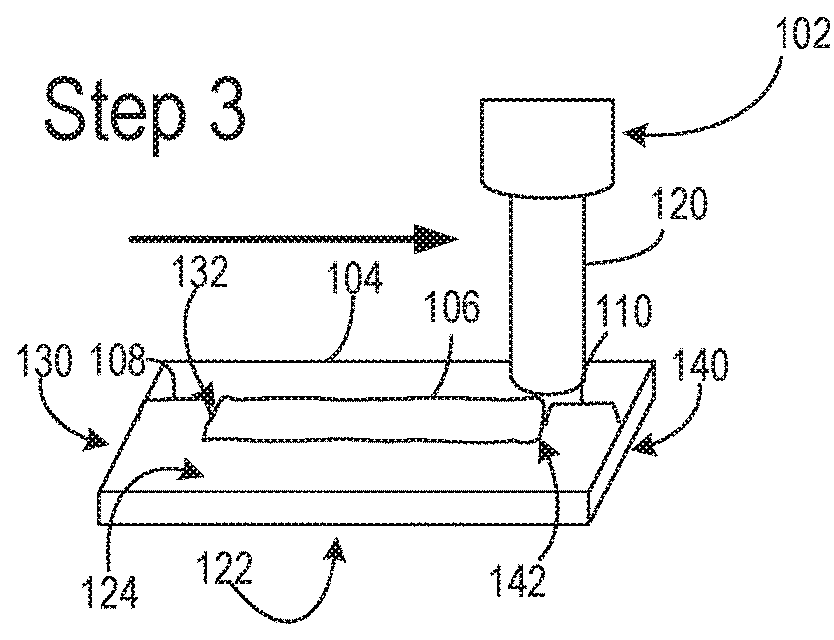
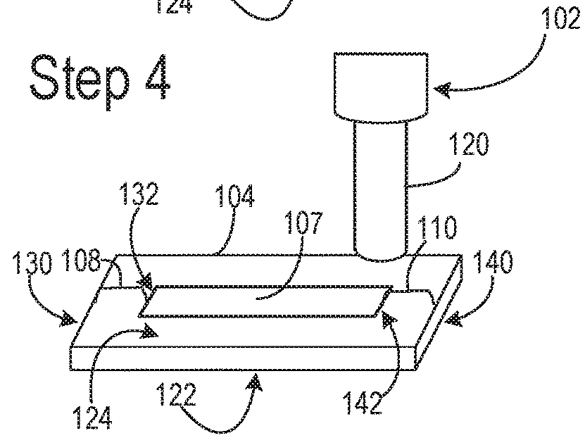
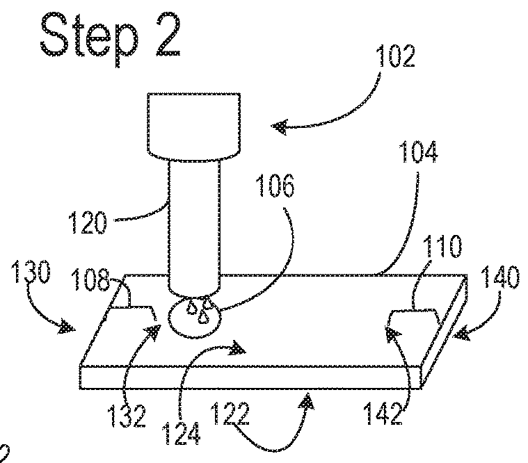
However, the inventors herein have recognized potential issues with such systems.
As one example, the LFA devices by Freitag et al. and others are cumbersome and labor intensive to produce because of the cutting and assembly steps required to fabricate the final device.
The process is time consuming and contributes a large fraction of the production cost as well as introducing variability between tests.
Further, the detection methods of current LFA devices are relatively crude.
Further, LFAs are generally designed to show a positive or negative result, which may no

Method used


Image

  • Nitrocellulose extrusion for porous film strips
  • Nitrocellulose extrusion for porous film strips
  • Nitrocellulose extrusion for porous film strips

Examples


example 1

Microarray Validation

[0284]For validation studies, a plurality of existing well known and well-characterized antigens representing nine pathogens are examined. Antigens (133 in total) corresponding to nine pathogens are printed, in duplicate, on nitrocellulose-coated glass ONCYTE® AVID chips in the form of a microarray. Additionally, human IgG and IgM and buffer are printed as positive and negative controls respectively. Imaging fiducials are printed for reference. The microarray is printed three times in three separate print runs to normalize results against printing variation. The 133 antigens and positive controls are printed at concentrations of 0.3, 0.1, 0.03, 0.01, 0.003, 0.001 mg / mL (˜1 nL per spot) in PBS / 0.001% Tween 20, an optimized buffer. The trace of detergent both reduces non-specific binding of protein to printing pins and other solid surfaces and increases fluidity and spot size.

[0285]Each of the three individual microarrays of 133 antigens is probed with standard, w...


PUM


Abstract

Methods and systems are provided making a porous nitrocellulose strip for use in a lateral flow test. The strip may be formed from a liquid polymer mixture dispensed onto the planar surface via a dispensing device positioned vertically above the planar surface. The strip may be printed with a microarray of binding ligands for use in the lateral flow test. Methods and systems are further provided for developing and viewing the results of the assay.

Description

CROSS REFERENCE TO RELATED APPLICATION[0001]The present application is a continuation-in-part of U.S. patent application Ser. No. 14 / 931,512, entitled “NITROCELLULOSE EXTRUSION FOR POROUS FILM STRIPS,” and filed on Nov. 3, 2015. U.S. Non-Provisional application Ser. No. 14 / 931,512 claims priority to U.S. Provisional Patent Application No. 62 / 075,126, entitled “NITROCELLULOSE EXTRUSION FOR POROUS FILM STRIPS,” and filed on Nov. 4, 2014. The entire contents of each of the above-listed applications are hereby incorporated by reference for all purposes.FIELD[0002]The present application generally relates to methods and systems for making nitrocellulose polymer films, methods and systems for casting those films, and the use of those films in the qualitative and quantitative analysis of biomolecules in a sample.BACKGROUND AND SUMMARY[0003]Lateral flow assays (LFA) use a porous polymeric film, usually comprising nitrocellulose (cellulose nitrate) on a carrier substrate, to provide a wickin...

Claims


Application Information

Patent Timeline
IPC IPC(8): B01L3/00G01N33/487G01N21/64
CPCB01L3/5023G01N33/4875B01L3/502715G01N21/6428B01L2300/0825B01L2300/025B01L2300/0609B01L2300/0636B01L2300/0645B01L2300/069B01L2300/088B01L2300/16B01L2300/12G01N2021/0112G01N2021/0346G01N2800/60G01N2035/00108G01N21/6452G01N2021/6419G01N2021/6421B01L2200/16B01L2300/021B01L2300/022B01L2400/0406B01L2400/0683
Inventor GREEF, CHARLESSNIDER, JOSHUAWEAVER, STEVENGRUDZIEN, JENNIPHER LYNMULLER, KELSEY ANNEMOODY, STEPHEN E.
Owner GRACE BIO-LABS
Why Eureka
Try Eureka