In-flight transfer of reactant from a towing or carrying airplane to an attached rocket or rocketplane

Active Publication Date: 2018-09-20
BURGENER JOHN A +2
View PDF0 Cites 13 Cited by
  • Summary
  • Abstract
  • Description
  • Claims
  • Application Information

AI Technical Summary

Benefits of technology

[0024]If the rocketplane is desired to land with power, it is necessary for the rocketplane to have either a rocket engine that can be run at variable speeds, allowing it to power the return flight to the airport and maintain control during landing, or the rocketplane will need jet engines to provide power during landing. If j et engines are added to the rocketplane, the rocketplane will have a higher dry weight, and a smaller payload to orbit. However, it also allows the rocketplane to takeoff with minimal fuel still enabling the minimal structural weight on takeoff, while avoiding the need for a tow to takeoff Logistically it is slightly easier to have two independent vehicles take off. However, to avoid the loss of altitude during fueling from the tanker, the rocketplane should first attach a tow cable to the tanker while in flight. Once attached to the tow cable, the fuel and oxidant lines could be attached, and the fuel and oxidant transfer be carried out without the towed rocketplane losing altitude. This is a lessor advantage than the tow from takeoff, but a better system than the inflight fueling without a tow cable attached.
[0025]It is also apparent that the main benefit of this disclosure is the concept of both starting flight with minimal fuel and/or oxidant on board the rocket or rocketplane, and transferring the fuel and/or oxidant while in flight and while both vehicles are securely attached so that the tanker airplane provides lift and velocity to the rocket or rocketplane. As such, it is also apparently equally beneficial for rockets and rocketplanes carried on airplanes, rather than being towed, to be carried with minimal fuel and/or oxidant on takeoff and to transfer the fuel and/or oxidant while in flight. When the carried roc

Problems solved by technology

However at present no single stage to orbit vehicles have been successfully built and flown to orbit.
The problem is the amount of fuel and oxidant required is approximately 97-98% of the total gross weight at launch.
Some companies are working on reusable early stages, but at present, most are used once and not able to be used a second time.
Some have returned safely, but at present most vertical landing systems have failed to land properly and it remains difficult to have a first stage return this way.
Usually the infrastructure to provide secure support before launch requires a system such as used for launches at the Kennedy Spaceport-which cost billions of dollars to build.
However, having an airplane-like vehicle for the first stage, or rocketplane, that can takeoff from a runway has some challenges.
This accomplishes the desired result of enabling the rocketplane to begin its flight at high altitude and with significant initial speed, but requires a very expensive dedicated vehicle to carry the rocket or rocketplane to altitude, and requires a complex and expensive procedure to connect the two vehicles before flight.
Also, the rocketplane still requires significant structural strength since the vehicle is still carrying the full fuel and oxidant load at the start of the flight.
The challenge has been

Method used


Image

  • In-flight transfer of reactant from a towing or carrying airplane to an attached rocket or rocketplane
  • In-flight transfer of reactant from a towing or carrying airplane to an attached rocket or rocketplane
  • In-flight transfer of reactant from a towing or carrying airplane to an attached rocket or rocketplane

Examples


first embodiment

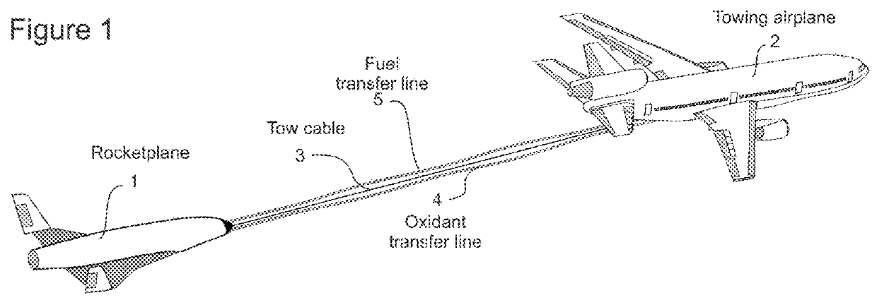
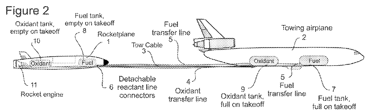
[0032]FIG. 1 shows a towing system according to the present disclosure. A rocketplane 1, otherwise referred to herein as a high altitude vehicle, is attached to a towing airplane 2 with a tow line or cable 3 strong enough to enabling the pulling of the rocketplane without breaking. An oxidant transfer line 4 and a fuel transfer line 5 are attached between the rocketplane and the towing airplane but are not supporting or towing the rocketplane, and may be separately attached between the rocketplane and the towing airplane, or may be secured to each other or to the tow line. The transfer of fuel and / or oxidant between the towing airplane and rocketplane occurs while they are securely attached and in flight. How and when the tow line is attached is not critical to the process. The cable may be attached before takeoff, and the towing airplane tows the rocketplane from the beginning of flight, or it may be attached while in flight, in which case the towing airplane only tows the rocketpl...

second embodiment

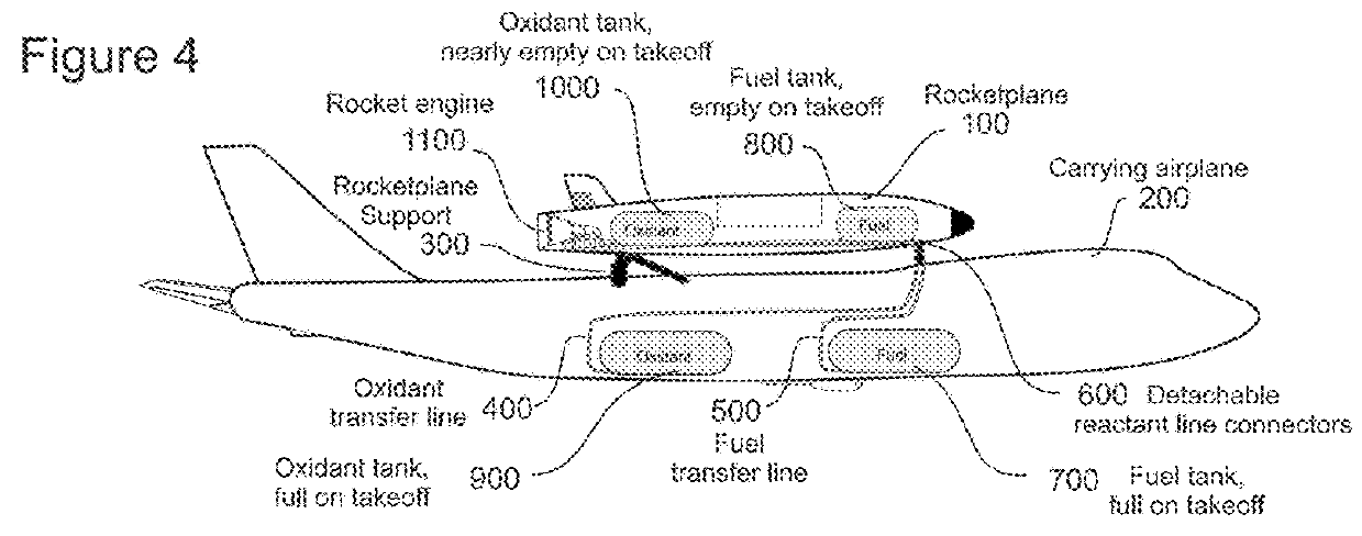
[0034]FIG. 3 shows a large airplane 200 carrying a rocketplane according to the present disclosure. In this figure, the rocketplane 100 is on the back of a carrying airplane 200 such as a Boeing 747. The rocketplane may be mounted anywhere convenient as long as it allows the carrying aircraft to fly safely. For example, the rocketplane may be mounted on top, on the belly, on a wing or under a wing of the carrying plane. The size of the rocketplane will be a major determining factor in its placement. In all variations of placement, having the fuel and oxidant tanks empty in the rocketplane prior to launch preparation allows simpler mounting and carrying of the rocketplane with minimal change in the center of gravity for the carrying airplane.

[0035]FIG. 4 shows a cross section of the carrying airplane 200 and the carried rocketplane 100. The rocketplane 100 is attached to the carrying airplane 200 with supports 300 able to carry the rocketplane safely and to release the rocketplane wh...


PUM


Abstract

A high altitude vehicle is brought to a desired altitude above sea-level prior to the transfer of fuel and/or oxidant from an airplane to the high altitude vehicle. The high altitude vehicle may be towed to the desired altitude by a tow airplane or may reach the desired altitude under its own power. At the desired altitude, the high altitude vehicle is connected to the tow airplane via a tow cable. Alternatively, the high altitude vehicle may be mechanically carried by the tow airplane. Fuel and/or oxidant is transferred to the high altitude vehicle from the tow airplane via respective fuel and/or oxidant lines. The high altitude vehicle then separates from the tow airplane and proceeds to high altitude under its own power.

Description

STATEMENT REGARDING FEDERALLY SPONSORED RESEARCH OR DEVELOPMENT[0001]n / aBACKGROUND OF THE INVENTION[0002]Disclosed are concepts related to rockets used to launch payload such as satellites into orbit. Re-usable rockets would dramatically reduce the cost of launch services. Starting a launch while at higher altitudes enhances the performance of the rocket engines, and if traveling at airplane cruising speed, the cruising speed is added to the rocket's final velocity, improving its payload size and weight capabilities or increasing its final speed and altitude. Various methods have been proposed to assist a rocket to allow it to start powered flight at altitude.[0003]Satellites have become a necessary part of life in the last 50 years. We use GPS to navigate our cars, airplanes and ships. We use satellites for internet, radio, TV and cell phones. Government satellites monitor the weather, climate and activities on Earth. Google Earth allows us to see the entire planet from satellite v...

Claims


Application Information

Patent Timeline
IPC IPC(8): B64D39/00B64D5/00B64C39/02B64G1/14B64G1/00B64D27/02
CPCB64D39/00B64D5/00B64C39/024B64C2201/146B64G1/005B64D27/023B64C2201/141B64G1/14B64D3/00B64G1/402Y02T50/40B64U50/15B64U10/25B64U2201/20
Inventor BURGENER, JOHN A.CLAPP, MITCHELL BURNSIDEDELONG, DANIEL LEE
Owner BURGENER JOHN A
Why Eureka
Try Eureka