Electrically conductive polymer film

a polymer film and conductive technology, applied in the direction of conductors, instruments, transportation and packaging, etc., can solve the problems of non-uniform defrosting using these methods, increased manufacturing and increased production steps for windows and mirrors with embedded wires or printed circuits

Inactive Publication Date: 2018-09-20
APTIV TECH LTD
View PDF15 Cites 10 Cited by
  • Summary
  • Abstract
  • Description
  • Claims
  • Application Information

AI Technical Summary

Benefits of technology

[0006]The polymeric base material may be polyethylene, polypropylene, polyvinyl chloride, polycarbonate, acrylic, polyester, or polyamide material. The plurality of electrically conductive nanoparticles may be metallic nanowires, metal-plated nanofibers, carbon nanotubes, graphene nanoparticles, and / or graphene oxide nanoparticles. The plurality of electrically conductive nanoparticles may comprise 0.01% to 0.1% by weight of the electrically conductive polymer film. The plurality of electrically conductive nanoparticles may also or alternatively include an inherently conductive polymer. The inherently conductive polymer may be one or more of the following: polylanine, 3,4-ethylenedioxythiophene, 3,4-ethylenedioxythiophene polystyrene sulfonate, and / or 4,4-cyclopentadithiophene. The plurality of electrically conductive nanoparticles may be substantially uniformly distributed throughout the polymeric base material.

Problems solved by technology

However, routing additional ductwork to carry heated air from the HVAC system to other window surfaces, such as the vehicle's rear window or outside mirrors, has been found to the uneconomical and / or ineffective.
Defrosting using these methods is non-uniform, as the area around the resistive circuits will heat up first.
Additionally, production of windows and mirrors with embedded wires or printed circuits require manufacturing steps additional steps.
The printed circuits are also easily damaged by abrasion or cracking.

Method used


Image

  • Electrically conductive polymer film
  • Electrically conductive polymer film
  • Electrically conductive polymer film

Examples


Embodiment Construction

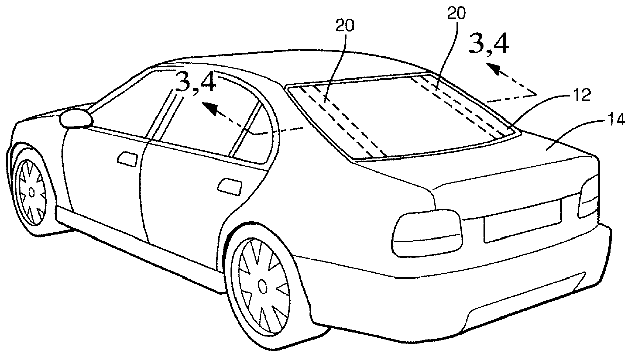
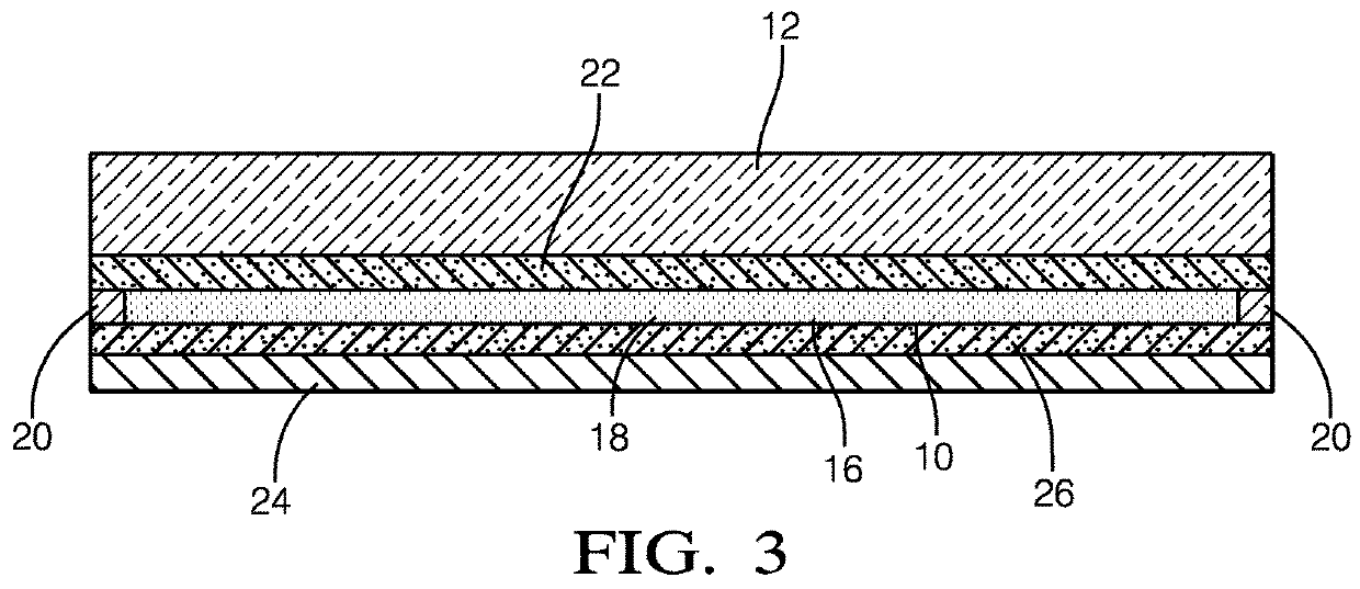
[0017]An electrically conductive polymer film that can be applied to windows, mirrors, sensors, lights, and other devices to provide defrosting capabilities is presented herein. The film is formed of a polymeric base material and includes electrically conductive nanoparticles that are randomly oriented in the polymeric material and interconnected to form an electrical network. Without subscribing to any particular theory of operation, when an electrical current is applied to the film through a pair of conductive electrodes , the electrical power dissipated within the film causes the film to heat, thereby defrosting the device to which the film is applied.

[0018]Low loadings of conductive nanoparticles within a transparent polymeric material in the range of 0.01% to 0.1% by weight have been shown to create an electrically conductive polymer film with transparent properties. Suitable transparent polymeric materials include polyethylene, polypropylene, polyvinyl chloride, polycarbonate,...


PUM

PropertyMeasurementUnit
electrically conductiveaaaaaaaaaa
transparentaaaaaaaaaa
conductiveaaaaaaaaaa

Abstract

An electrically conductive polymer film is presented. The electrically conductive polymer film includes a polymeric base material, a plurality of electrically conductive nanoparticles randomly oriented within the polymeric base material, and a pair of electrodes electrically interconnected with the plurality of electrically conductive nanoparticles. The electrodes are configured to be connected to an electrical power source. The polymeric base material may e.g. be polyethylene, polypropylene, polyvinyl chloride, polycarbonate, acrylic, polyester, and/or polyamide. The plurality of electrically conductive nanoparticles may be metallic nanowires, metal-plated nanofibers, carbon nanotubes, graphene nanoparticles, and/or graphene oxide nanoparticles. The plurality of electrically conductive nanoparticles may also or alternatively include an inherently conductive polymer such as polylanine, 3,4-ethylenedioxythiophene, 3,4-ethylenedioxythiophene polystyrene sulfonate, and/or 4,4-cyclopentadithiophene. The plurality of electrically conductive nanoparticles may be substantially uniformly distributed throughout the polymeric base material.

Description

TECHNICAL FIELD OF THE INVENTION[0001]The invention generally relates to an electrically conductive polymer film, and more particularly relates to an electrically conductive polymer film suitable for use in defroster and / or defogger applications.BACKGROUND OF THE INVENTION[0002]Warm air from a vehicle's heating, ventilation, and air conditioning (HVAC) system is typically used to remove fogging, frost, snow, and ice, from a vehicle's windshield and front side windows, hereinafter generically referred to as defrosting. However, routing additional ductwork to carry heated air from the HVAC system to other window surfaces, such as the vehicle's rear window or outside mirrors, has been found to the uneconomical and / or ineffective. Therefore, secondary defrosting systems using resistive heating to defrost rear windows and mirrors and typically include resistive wires embedded within the glass or resistive circuits printed on an interior surface of the glass as shown in FIG. 1. Defrosting...

Claims


Application Information

Patent Timeline
Patent Type & Authority Applications(United States)
IPC IPC(8): G02B27/00B60R1/06G02B1/14B60J1/00H05B3/84H05B3/14
CPCG02B27/0006B60R1/0602G02B1/14B60J1/002H05B3/845H05B2214/02H05B3/146H01B1/22H01B1/24H01B1/124H05B2203/013H05B3/84G02B7/1815H05B2214/04
Inventor RICHMOND, ZACHARY J.RUBINO, EVANGELIA
Owner APTIV TECH LTD
Why Eureka
Try Eureka