
High-low-voltage conversion star multi-phase variable-frequency drive system

Active Publication Date: 2018-10-04
WOLONG ELECTRIC GRP CO LTD
View PDF0 Cites 6 Cited by
  • Summary
  • Abstract
  • Description
  • Claims
  • Application Information

AI Technical Summary

Benefits of technology

The patent describes a high-low-voltage conversion star multi-phase variable-frequency drive system that can efficiently convert high-voltage power into low-voltage three-phase alternating-current power. The system includes a phase-shifting transformer, rectifying circuits, inverter circuits, and a control circuit. The number of secondary windings is the same as the number of rectifying circuits, which are connected in a common-ground direct-current power source. The system also includes a cooling structure that simplifies the cooling process and increases the selection range of cooling modes. The technical effects of this system include reducing insulation requirements, improving heat dissipating ability, and increasing power density. Additionally, the system allows for pole-changing and phase-changing operation through adjustment of control policies, and improves speed ratio without increasing eddy-current loss of the motor.

Problems solved by technology

Variable-frequency drive technical solutions which are commonly used at present are mainly centralized on adding a frequency converter to a common motor, do not consider a variable-frequency motor and a variable-frequency speed control system as one system architecture, and have some limitations.
For example, the most commonly used drive solution is that a high-voltage three-phase motor is added with cascade high-voltage frequency converters, weaknesses thereof lie in that levels of a plurality of independent H bridges of each phase are different, insulation treatment must be performed and it is difficult to realize liquid heat dissipation and cooling; although a three-level variable-frequency speed control solution can solve the problem of common ground of power devices, due to the limitations of withstand voltage and current of power devices, high-voltage and large-current output cannot be realized; although a multi-level variable-frequency speed control solution can break through certain voltage limitations, voltage sharing technique and hardware structure are very complex; and a two-level three-phase variable-frequency speed control solution is restricted by voltage and current.
On a motor side, due to the increase of power supply voltage, the requirements on insulating systems and manufacturing processes of high-voltage motors are also greatly increased, the insulation life of motors is reduced, the manufacturing process cost is increased, the heat dissipation conditions of motors become poor and the power density is decreased.

Method used


Image

  • High-low-voltage conversion star multi-phase variable-frequency drive system
  • High-low-voltage conversion star multi-phase variable-frequency drive system
  • High-low-voltage conversion star multi-phase variable-frequency drive system

Examples


embodiment 2

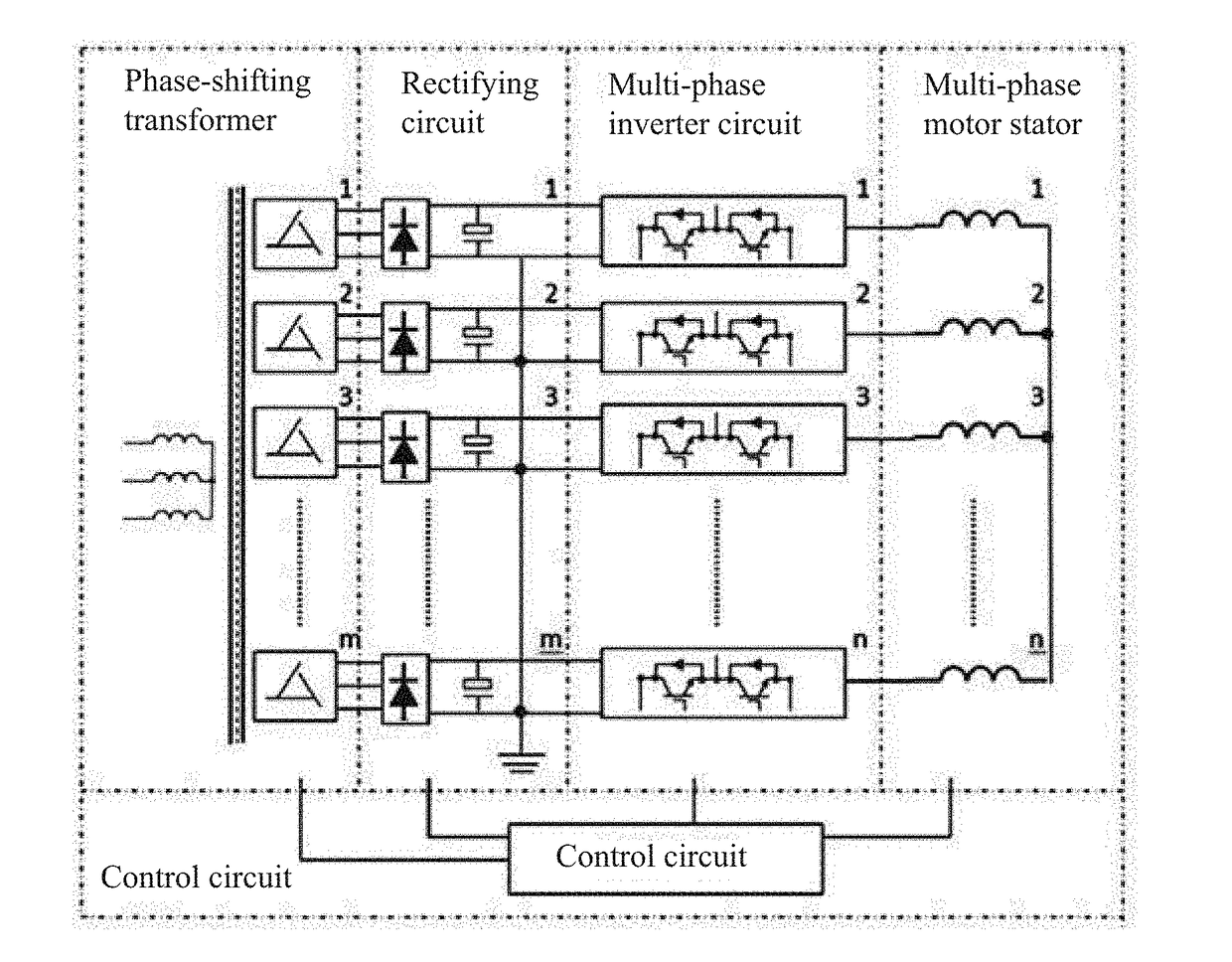
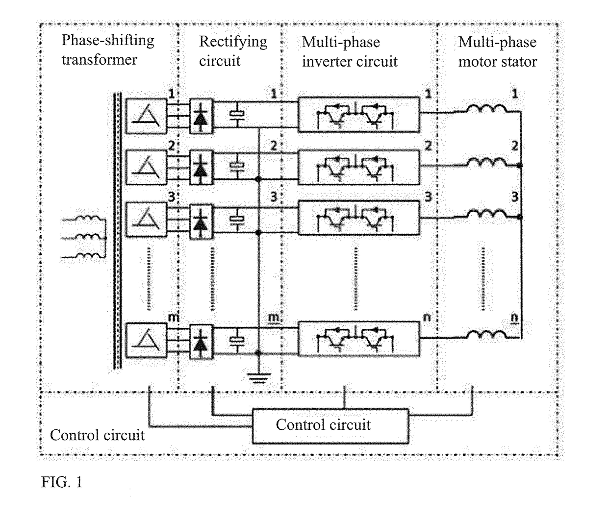
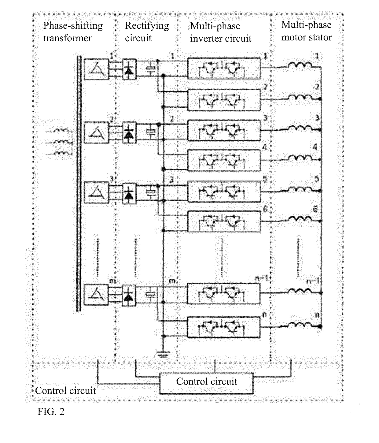
[0030]Differences from embodiment 2 lie in that:

[0031]In order to simplify the structure of the phase-shifting transformer, when the phases of the motor are enough, the effect that one secondary phase-shifting winding provides power to a plurality of units can be realized; and as illustrated in FIG. 2, when the number of the inverter circuits is integral times of the number of the rectifying circuits, i.e., n / m=k (natural number), input ends of any k inverter circuits are connected in parallel to form m inverter circuit parallel groups, and an input of each inverter circuit parallel group is then connected with an output of each rectifying circuit.

[0032]The high-low-voltage conversion star multi-phase variable-frequency drive systems illustrated in FIG. 1 and FIG. 2 are specific embodiments of the present invention, the prominent substantive features and notable progress of the present invention have already been reflected, and equivalent modifications made in aspects such as shape ...


PUM


Abstract

The present invention provides a high-low-voltage conversion star multi-phase variable-frequency drive system and relates to a high-voltage high-power motor and drive control thereof. The variable-frequency drive technical solution which is commonly used at present mainly has the disadvantages that a frequency converter is added to a common motor, the insulation life of the motor is short and the heat dissipating ability of the motor is poor. The system comprises a phase-shifting transformer, rectifying circuits, inverter circuits, a multi-phase motor, and a control circuit connected with the phase-shifting transformer, the rectifying circuits, the inverter circuits and the multi-phase motor, wherein primary windings of the phase-shifting transformer are connected with an alternating-current power source, and secondary windings of the phase-shifting transformer are connected with the rectifying circuits; and is characterized in that the number of the secondary windings is the same as the number of the rectifying circuits, one secondary winding is connected with one rectifying circuit, all rectifying circuits are in common-ground connection to form a common-ground direct-current power source, and output ends of the rectifying circuits are connected with the inverter circuits. By adopting the technical solution, high voltage and large currents are realized, simultaneously the structure is simple, the insulation requirement is lowered, the heat dissipating ability of the motor is improved and the power density is increased.

Description

FIELD OF THE INVENTION[0001]The present invention relates to a high-voltage high-power motor and drive control thereof, in particular to a high-low-voltage conversion star multi-phase variable-frequency drive system, and belongs to the field of electrical motors and control thereof.BACKGROUND OF THE INVENTION[0002]Variable-frequency speed control of high-power motors is an important means to improve energy efficiency of motors. With the continuous progress of power electronic devices, high-power motor variable-frequency speed control systems are widely applied. Variable-frequency drive technical solutions which are commonly used at present are mainly centralized on adding a frequency converter to a common motor, do not consider a variable-frequency motor and a variable-frequency speed control system as one system architecture, and have some limitations. For example, the most commonly used drive solution is that a high-voltage three-phase motor is added with cascade high-voltage freq...

Claims


Application Information

Patent Timeline
IPC IPC(8): H02P23/28H02P23/12H02P25/18H02P27/06H02P29/028H02P29/50
CPCH02P23/28H02P23/12H02P25/18H02P27/06H02P29/028H02P29/50H02P25/16H02M7/483H02M7/539H02M7/5395H02P25/20H02P27/08
Inventor WANG, JIANQIAOWU, XUANDONGLIAN, CHENLONGYAN, WEICAN
Owner WOLONG ELECTRIC GRP CO LTD
Learn More