
Fluorescence calibration slide

Active Publication Date: 2018-10-11
KONINKLJIJKE PHILIPS NV
View PDF7 Cites 4 Cited by
  • Summary
  • Abstract
  • Description
  • Claims
  • Application Information

AI Technical Summary

Benefits of technology

The patent describes a calibration slide that uses plasmon resonance to produce light for calibrating a fluorescence microscope. This calibration slide has a broad absorption and emission spectrum that covers all typical fluorescence channels. It can be used to calibrate multiple fluorescence dyes and is stable in time without showing bleaching or degradation. The thin layer of metal nanostructures on the calibration slide ensures homogeneous fluorescence intensity across the slide and is suitable for applications like digital pathology. Overall, this calibration slide offers a more efficient and reliable way to calibrate fluorescence microscopes.

Problems solved by technology

However, after long-term usage, the scanning accuracy of a fluorescence imaging system may fluctuate or even decline, e.g. due to malfunctioned optics arrangement of the fluorescence microscope.

Method used


Image

  • Fluorescence calibration slide
  • Fluorescence calibration slide
  • Fluorescence calibration slide

Examples


Embodiment Construction

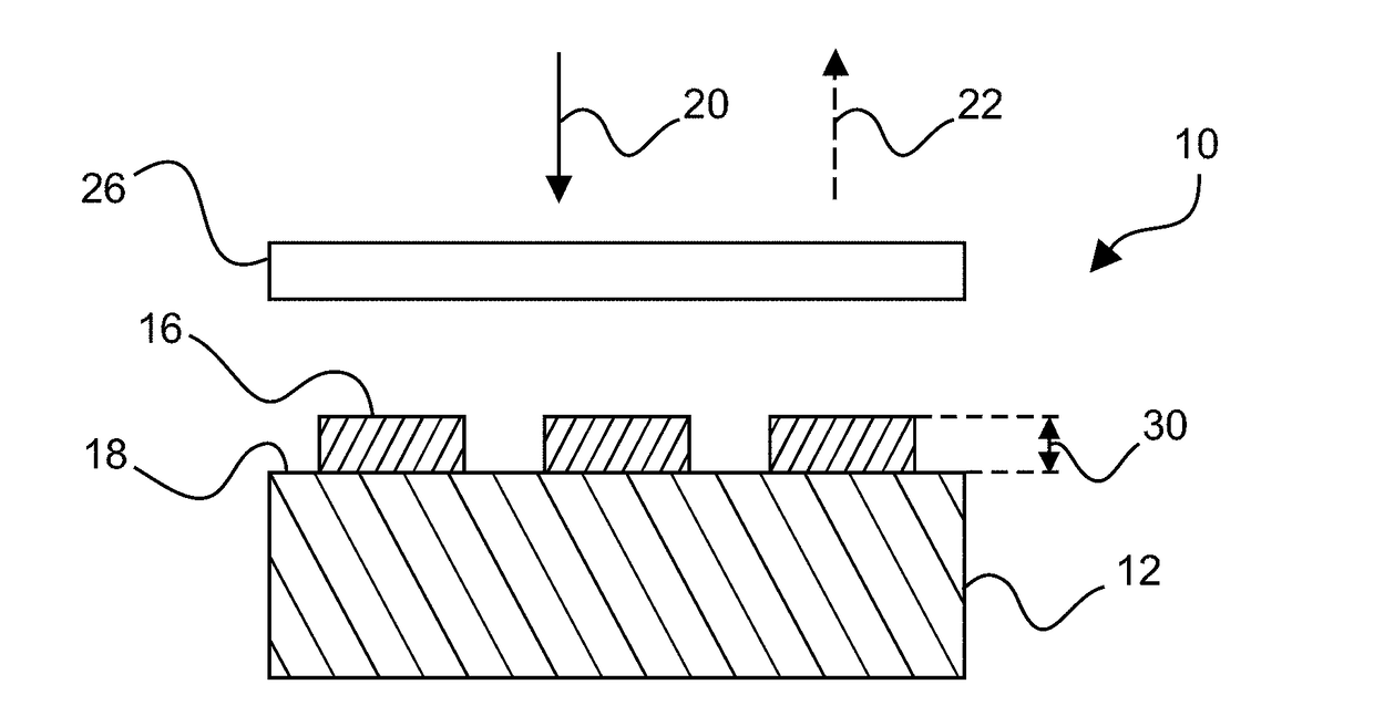
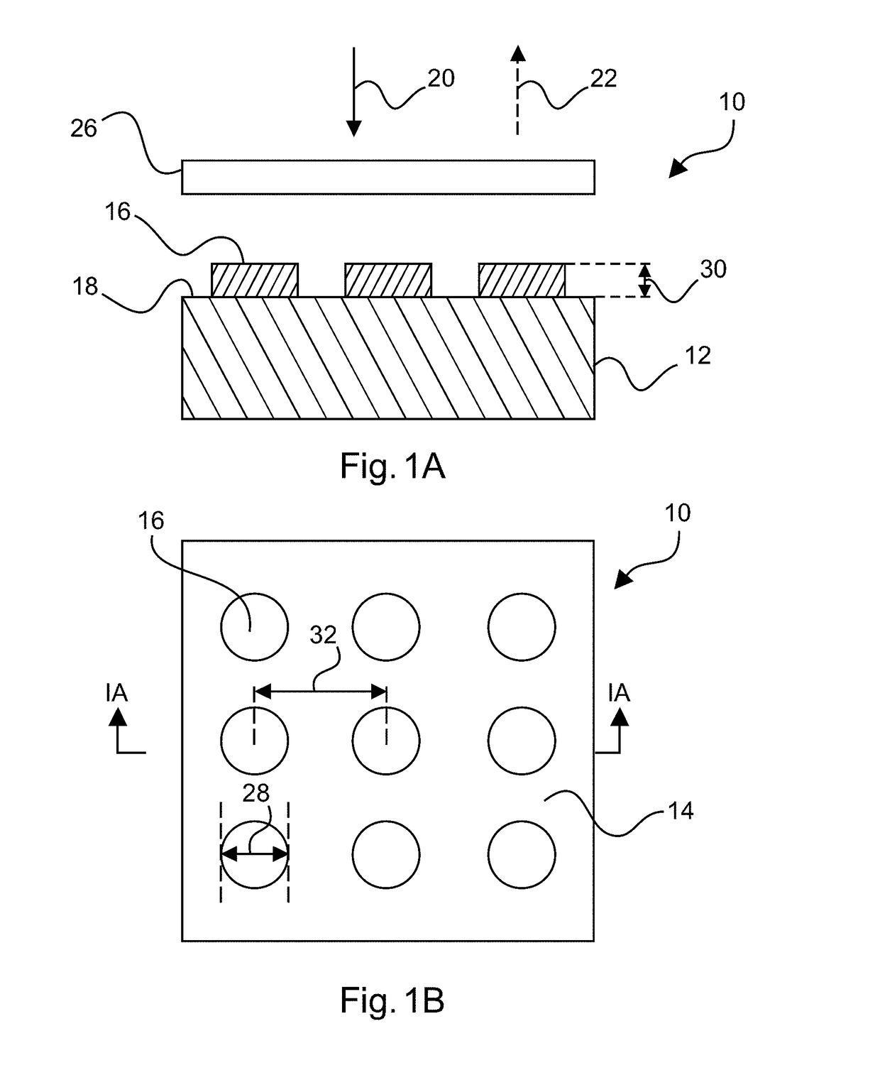
[0052]FIG. 1B shows a top view of an example of a calibration slide 10 for a fluorescence microscope 42 (see an example in FIG. 7). FIG. 1A shows a sectional view along a line 1A-1A shown in FIG. 1B.

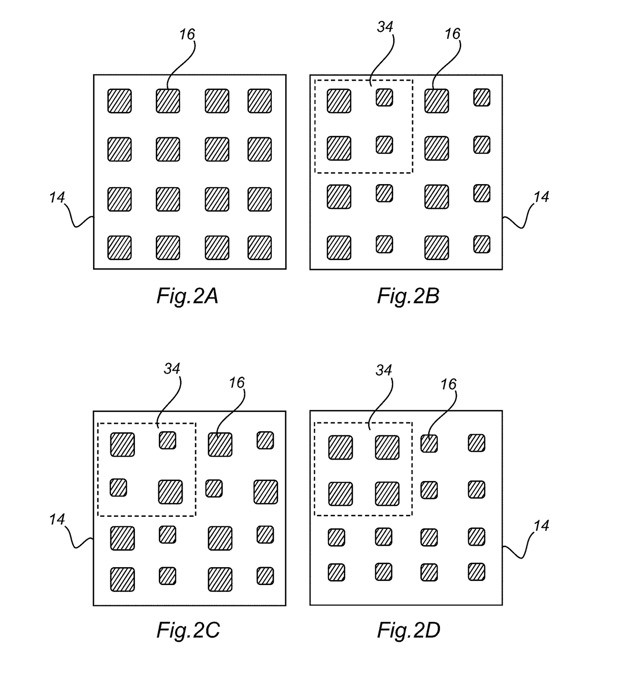
[0053]The calibration slide 10 comprises a substrate 12 and a pixel layout 14 with a plurality of spaced apart metal nanostructures 16 arranged on a surface 18 of the substrate 12. The metal nanostructures 16 are arranged to produce plasmon resonances that allow absorbing light 20 at an excitation wavelength, indicated with a solid arrow, to produce photo-luminescence and / or fluorescence light 22, indicated with a dashed arrow, for generating a fluorescent image. The fluorescent image comprises a plurality of pixel intensity values that are provided for calibration of the fluorescence microscope.

[0054]Optionally, a cover slip 26 is provided for covering and protecting the pixel layout 14. For mounting the optional cover slip 20, it is possible to use glue, resin, or any other appropriate...


PUM


Abstract

The present invention relates to fluorescence imaging. In order to enhance compatibility with multiple fluorescence channels for calibrating a fluorescence microscope, a calibration slide is provided that comprises a substrate and a pixel layout. The pixel layout comprises a plurality of spaced apart metal nanostructures arranged on a surface of the substrate. The metal nanostructures are arranged to produce plasmon resonances that allow absorbing light at an excitation wavelength to produce photo-luminescence and / or fluorescence light for generating a fluorescent image. The fluorescent image comprises a plurality of pixel intensity values that are provided for calibration of a fluorescence microscope.

Description

CROSS-REFERENCE TO RELATED APPLICATIONS[0001]This patent application is a continuation-in-part application that claims the priority benefit under 35 U.S.C. § 111(a) of International Patent Application No. PCT / EP2016 / 082352, filed Mar. 24, 2016, which claims the benefit of European Patent Application No. 15202526.8, filed on Dec. 23, 2015. These applications are hereby incorporated by reference herein in their entirety.FIELD OF THE INVENTION[0002]The present invention relates to the field of fluorescence imaging, and in particular to a calibration slide, to a calibration system of a fluorescence microscope, and to a method for calibrating a fluorescence microscope.BACKGROUND OF THE INVENTION[0003]Fluorescence imaging has been used in e.g. biology, medicine, and materials science. For example, in digital pathology, fluorescence imaging enables multi-channel scanning of fluorescently labeled slides, helping researches get more information from their samples. However, after long-term us...

Claims


Application Information

Patent Timeline
IPC IPC(8): G01N21/27G02B21/16G01N21/64
CPCG01N21/278G02B21/16G01N21/6458G01N21/648G01N2021/6482G02B21/34G01N21/64
Inventor BOAMFA, MARIUS IOSIFVALSTER, SUSANNE MAAIKEVERSCHUUREN, MARCUS ANTONIUS
Owner KONINKLJIJKE PHILIPS NV
Learn More