Eureka AIR delivers breakthrough ideas for toughest innovation challenges, trusted by R&D personnel around the world.

Automatic structurally induced line of sight jitter compensation for electro-optical/infrared turret system

Active Publication Date: 2018-11-01
RAYTHEON CO
View PDF2 Cites 3 Cited by
  • Summary
  • Abstract
  • Description
  • Claims
  • Application Information

AI Technical Summary

Benefits of technology

The present invention provides a light sensor system that uses a reference light source to improve jitter compensation and image quality. The reference light source moves in unison with the primary mirror and / or an inertial measurement device, and can compensate for elastic deformation of the optics and telescope optical axis. By directing the reference light source towards an obscured region of the light sensor system, the impact of the reference light source on the primary light detected can be minimized. The light sensor system includes a primary mirror that directs the reference light from the primary mirror along a path of the primary light through the light sensor system to the reference light sensor, which can detect structural movement of the primary mirror and other light reflectors. Overall, the invention provides a cost-effective light sensor system with improved image quality.

Problems solved by technology

However, during flight of the aircraft the telescope optical assembly and the optical sensor are subjected to random vibration causing optical elements to move relative to one another, resulting in image jitter, which can reduce image quality of full motion video or still images.
These materials tend to be expensive, which adds to the overall cost of the optical sensor system.
Additionally under large enough vibration input levels material stiffness alone will not provide the required optical system stability and image quality will be impacted regardless of cost and complexity in telescope design.

Method used


Image

  • Automatic structurally induced line of sight jitter compensation for electro-optical/infrared turret system
  • Automatic structurally induced line of sight jitter compensation for electro-optical/infrared turret system
  • Automatic structurally induced line of sight jitter compensation for electro-optical/infrared turret system

Examples


Embodiment Construction

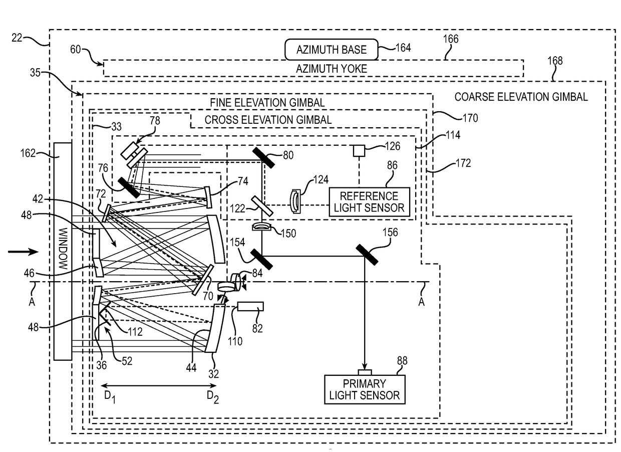
[0029]The principles of this present application have particular application to reducing the effects of jitter for aircraft light sensor systems, for example electro-optical / infrared turret systems that have a Three Mirror Anastigmat (TMA) form telescope to magnify the image of a target object, and thus will be described below chiefly in this context. It will be appreciated that principles of this invention may be applicable to other light sensor systems where it is desirable to reduce the effects of jitter, such as other telescope forms.

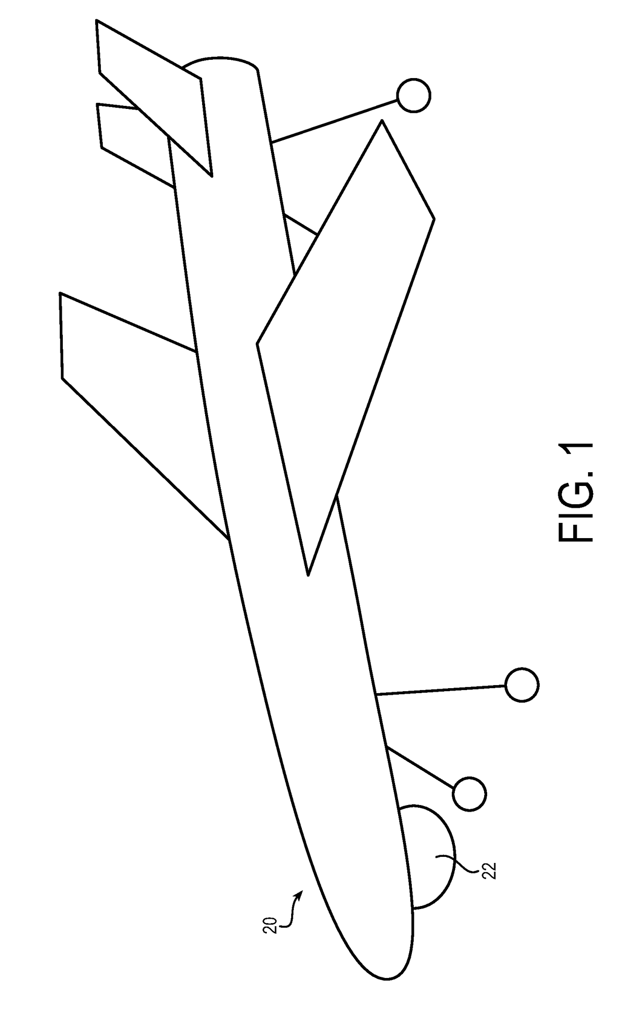
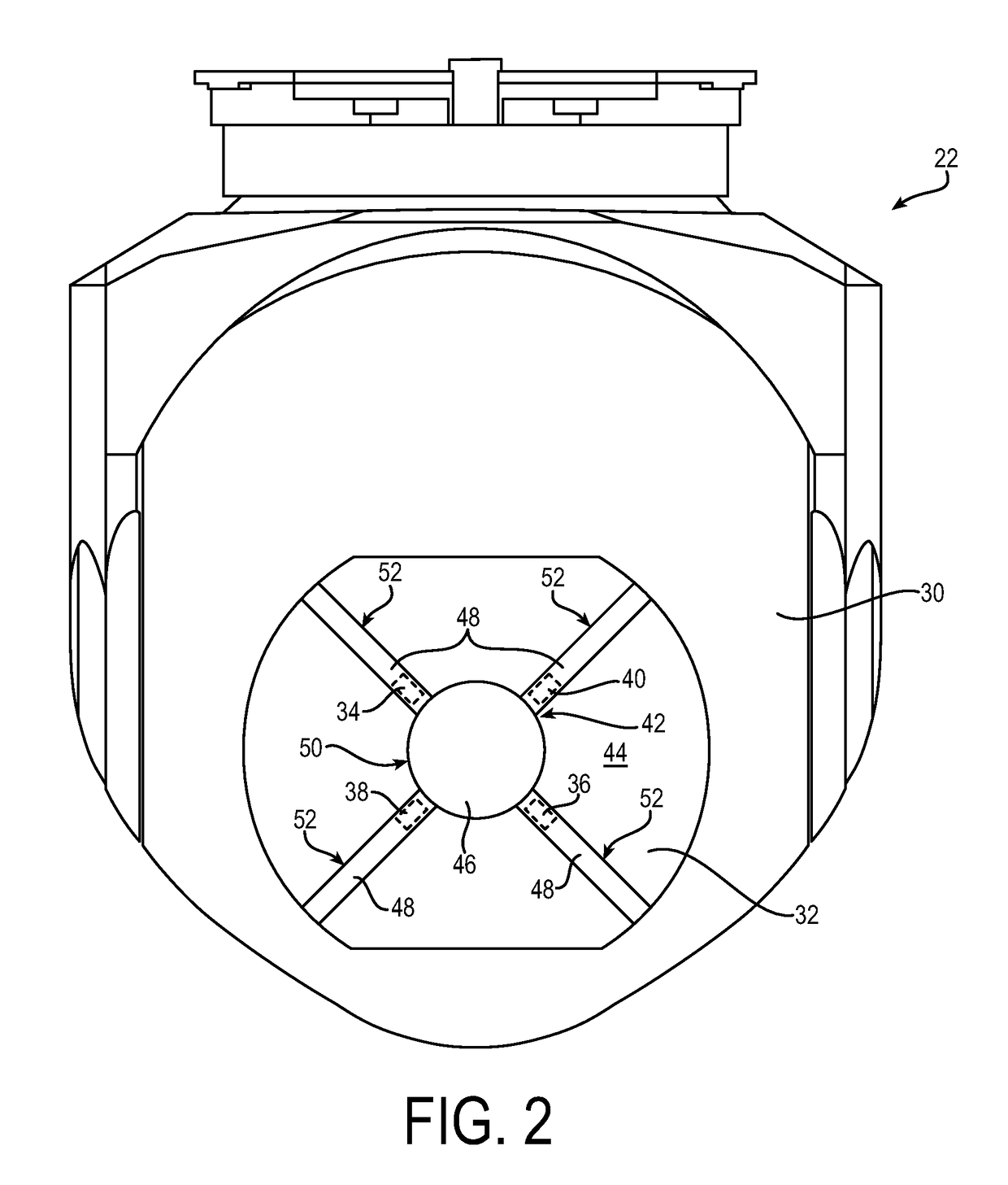
[0030]Referring now to the drawings and initially to FIG. 1, an exemplary aircraft is designated generally by reference numeral 20. The aircraft 20 can be provided with an exemplary light sensor system 22. The light sensor system 22 may capture images of primary light received from a target object, such as an infrared heat signature of a vehicle thousands of feet below the aircraft 20. In an embodiment, the aircraft is another type of vehicle, such ...


PUM


Abstract

A light sensor system including a reference light source that moves in unison with a primary mirror and / or an inertial measurement device, and / or the reference light source is directed toward an obscured region of the light sensor system. The reference light source may allow for improved jitter compensation based on feedback of the reference light. The feedback may be representative of the elastic deformation of the optics and telescope optical axis. The improved jitter compensation may allow for the light sensor system (e.g., the housing and / or mirrors) to be built with less stiff materials, which can reduce the cost of manufacturing the present light sensor system compared to previously known optical sensor systems. In cases of high vibration levels which would otherwise degrade the resulting image quality after material stiffness property selections have been exhausted, the light sensor system may provide jitter compensation to improve video or still image quality.

Description

GOVERNMENT LICENSE RIGHTS[0001]This invention was made with Government support. The Government has certain rights in the invention.FIELD OF INVENTION[0002]The present invention relates generally to jitter compensation, and more particularly to jitter compensation for electro-optical / infrared turret systems for aircraft.BACKGROUND[0003]Some aircraft have a gimbaled optical sensor system. The optical sensor system may be used to detect target objects that are located great distances from the aircraft. For example, the optical sensor systems detect target objects that are below the aircraft while the aircraft is in flight.[0004]The optical sensor systems often include an optical sensor and a telescope optical assembly to magnify the light received by the optical sensor to allow the optical sensor to capture images of the target object at great distances. However, during flight of the aircraft the telescope optical assembly and the optical sensor are subjected to random vibration causin...

Claims


Application Information

Patent Timeline
IPC IPC(8): H04N5/232H01L27/146G01P13/00B60Q1/00
CPCH04N5/23264H01L27/14629G01P13/00B60Q1/0041G01B11/272G02B27/646H04N23/682
Inventor MILLER, KIRK A.BAKER, CHRISTOPHER J.MILLER, STEVEN A.NORMAN, WALTER W.MARR, LYALE F.SCOTT, RICHARD L.
Owner RAYTHEON CO
Why Eureka
Eureka Blog
Learn More