
Surge protective device modules including integral thermal disconnect mechanisms and methods including same

Active Publication Date: 2018-11-15
RAYCAP IP DEV LTD
View PDF6 Cites 14 Cited by
  • Summary
  • Abstract
  • Description
  • Claims
  • Application Information

AI Technical Summary

Benefits of technology

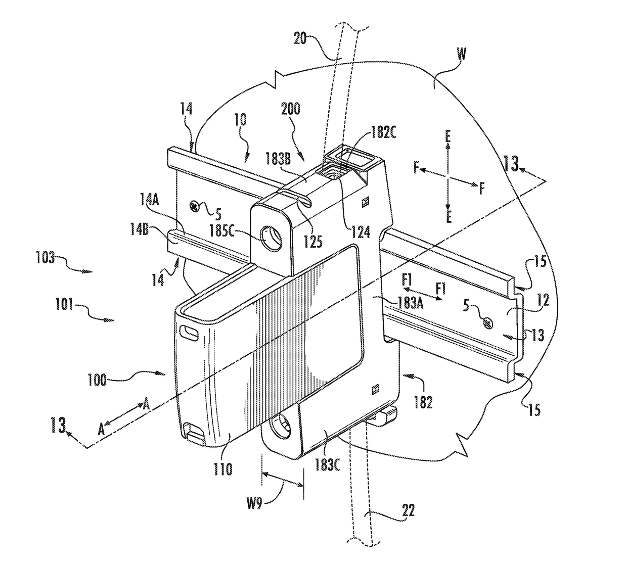
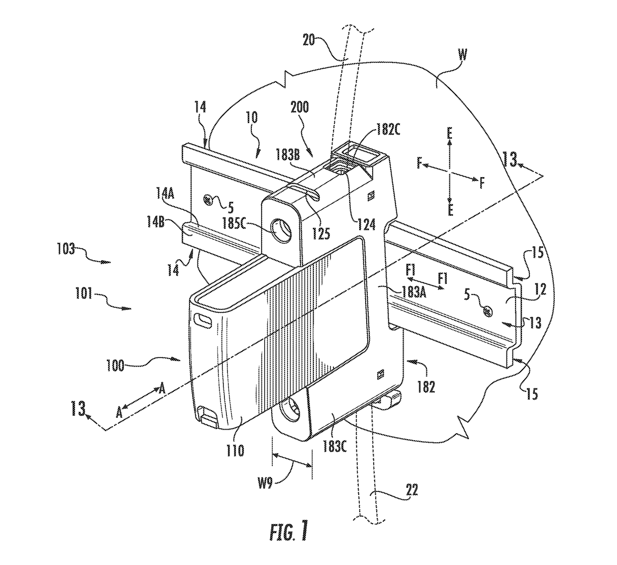
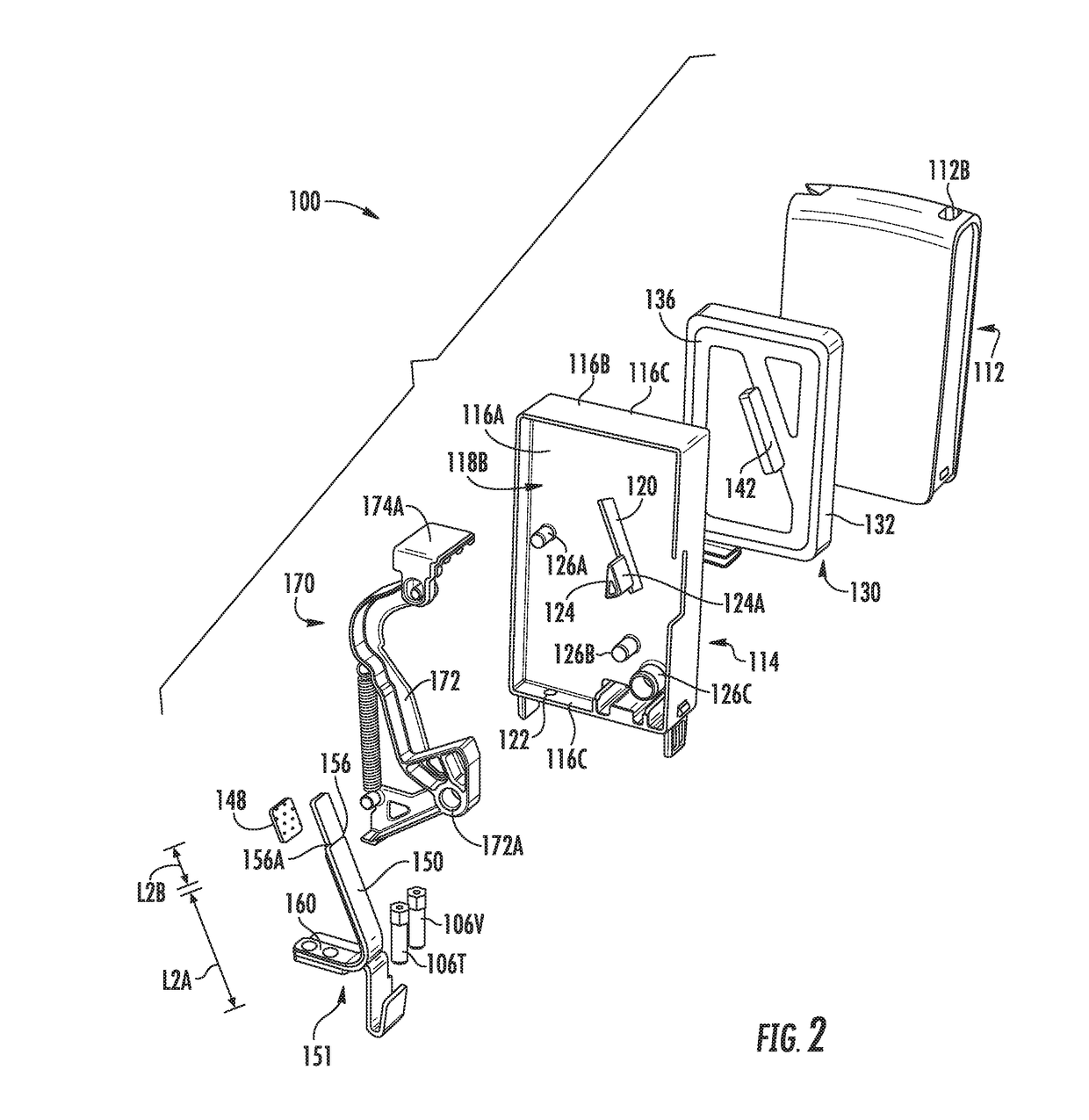
The invention is for a surge protective device (SPD) module that has an overvoltage clamping element and a thermal disconnector mechanism. The thermal disconnector mechanism is designed to disconnect the overvoltage clamping element from the second module electrical terminal if there is a surge current through the module. The module includes a heat sink member that has a thermal capacity to prevent the solder from melting in response to the heat from the overvoltage clamping element. The supplemental spring is connected to the electrode and provides thermal capacity to cool the disconnect spring. The technical effect of this invention is to provide a reliable surge protective device that can effectively protect the electrical equipment from surge currents without causing damage.

Problems solved by technology

Frequently, excessive voltage or current is applied across service lines that deliver power to residences and commercial and institutional facilities.
Such excess voltage or current spikes (transient overvoltages and surge currents) may result from lightning strikes, for example.
The above events may be of particular concern in telecommunications distribution centers, hospitals and other facilities where equipment damage caused by overvoltages and / or current surges is not acceptable and resulting down time may be very costly.
Typical failure mode of an SPD is a short circuit.
However, in some cases, one or more SPDs may begin to allow a leakage current to be conducted even at voltages that are lower that the operating voltage of the SPDs.

Method used


Image

  • Surge protective device modules including integral thermal disconnect mechanisms and methods including same
  • Surge protective device modules including integral thermal disconnect mechanisms and methods including same
  • Surge protective device modules including integral thermal disconnect mechanisms and methods including same

Examples


Embodiment Construction

[0039]The present invention now will be described more fully hereinafter with reference to the accompanying drawings, in which illustrative embodiments of the invention are shown. In the drawings, the relative sizes of regions or features may be exaggerated for clarity. This invention may, however, be embodied in many different forms and should not be construed as limited to the embodiments set forth herein; rather, these embodiments are provided so that this disclosure will be thorough and complete, and will fully convey the scope of the invention to those skilled in the art.

[0040]It will be understood that when an element is referred to as being “coupled” or “connected” to another element, it can be directly coupled or connected to the other element or intervening elements may also be present. In contrast, when an element is referred to as being “directly coupled” or “directly connected” to another element, there are no intervening elements present. Like numbers refer to like elem...


PUM


Abstract

A surge protective device (SPD) module includes a module housing, first and second module electrical terminals mounted on the module housing, an overvoltage clamping element electrically connected between the first and second module electrical terminals, and a thermal disconnector mechanism. The thermal disconnector mechanism is positioned in a ready configuration, wherein the overvoltage clamping element is electrically connected with the second module electrical terminal. The thermal disconnector mechanism is repositionable to electrically disconnect the overvoltage clamping element from the second module electrical terminal. The thermal disconnector mechanism includes: an electrode electrically connected to the overvoltage clamping element; a disconnect spring elastically deflected and electrically connected to the electrode in the ready configuration; a solder securing the disconnect spring in electrical connection with the electrode in the ready configuration; and a heat sink member thermally interposed between the electrode and the solder, the heat sink member having a thermal capacity. The solder is meltable in response to overheating of the overvoltage clamping element. The disconnect spring is configured to electrically disconnect the overvoltage clamping element from the second module electrical terminal when the solder is melted. The thermal capacity of the heat sink member buffers and dissipates heat from the overvoltage clamping element to prevent the solder from melting in response to at least some surge currents through the SPD module.

Description

FIELD OF THE INVENTION[0001]The present invention relates to surge protective devices and, more particularly, to surge protective devices including thermal disconnectors and alerting mechanisms.BACKGROUND OF THE INVENTION[0002]Frequently, excessive voltage or current is applied across service lines that deliver power to residences and commercial and institutional facilities. Such excess voltage or current spikes (transient overvoltages and surge currents) may result from lightning strikes, for example. The above events may be of particular concern in telecommunications distribution centers, hospitals and other facilities where equipment damage caused by overvoltages and / or current surges is not acceptable and resulting down time may be very costly.[0003]Typically, sensitive electronic equipment may be protected against transient overvoltages and surge currents using surge protective devices (SPDs). For example, an overvoltage protection device may be installed at a power input of eq...

Claims


Application Information

Patent Timeline
IPC IPC(8): H01H85/02H01C7/12H01H85/04H01H85/20H01H85/47
CPCH01H85/0241H01C7/126H01H85/47H01H85/20H01H85/04H02H5/041H02H9/042H01H37/761H01H2037/762
Inventor VRHUNC, JUREKAMENSEK, SEBASTJANKNEZ, TADEJJURICEV, IGORTSOVILIS, THOMAS
Owner RAYCAP IP DEV LTD
Features
  • Generate Ideas
  • Intellectual Property
  • Life Sciences
  • Materials
  • Tech Scout
  • Unparalleled Data Quality
  • Higher Quality Content
  • 60% Fewer Hallucinations
Learn More