Techniques for percutaneous mitral valve replacement and sealing
Active Publication Date: 2018-12-06
CARDIOVALVE LTD
View PDF4 Cites 134 Cited by
Summary
Abstract
Description
Claims
Application Information
AI Technical Summary
This helps you quickly interpret patents by identifying the three key elements:
Problems solved by technology
Method used
Benefits of technology
[0052]the apparatus being configured such that sliding the control filaments in a first direction through the conduit facilitates expansion of the prosthetic valve, and sliding the control filaments in a second direction through the conduit facilit
Problems solved by technology
Regurgitation of blood from the ventricle into the atrium results in increased total stroke volume and decreased cardia
Method used
Image
Click on the blue label to locate the original text in one second.
Reading with bidirectional positioning of images and text.
Examples
Embodiment Construction
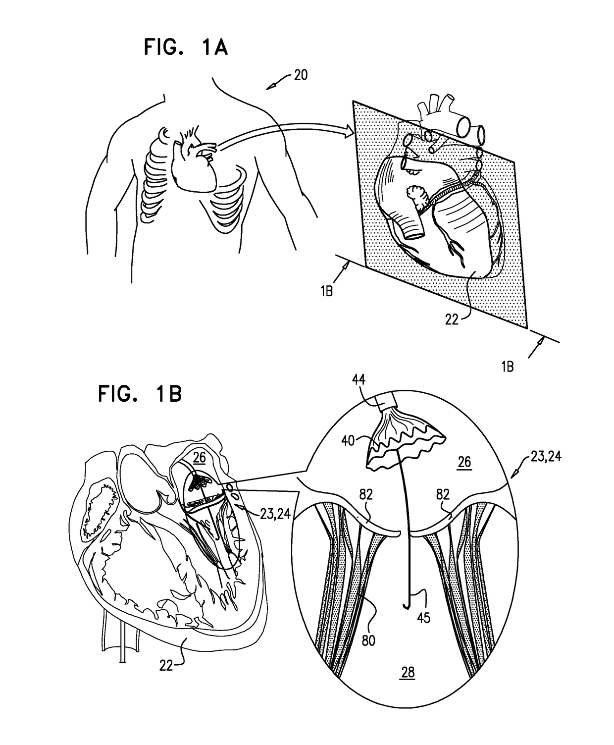
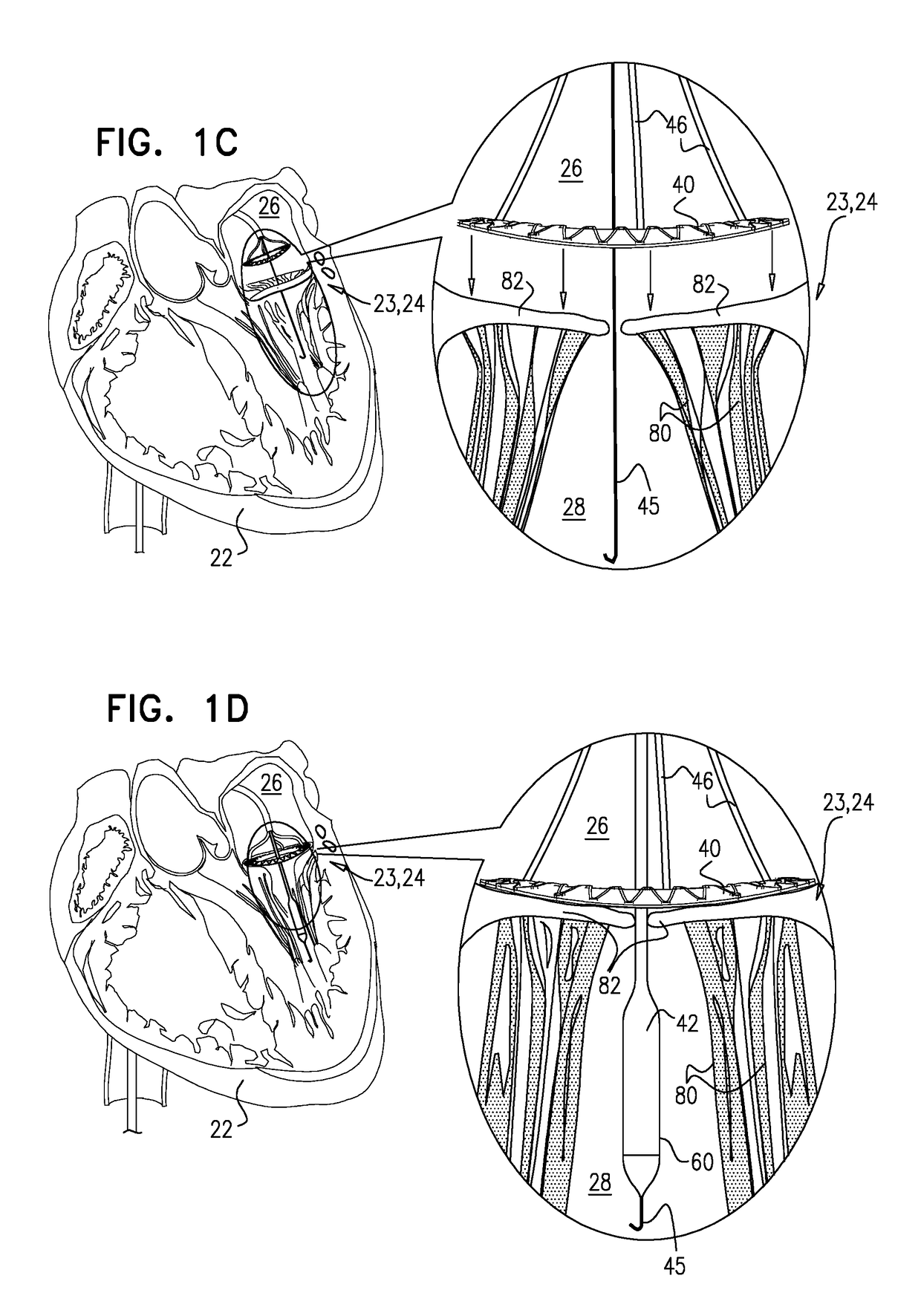
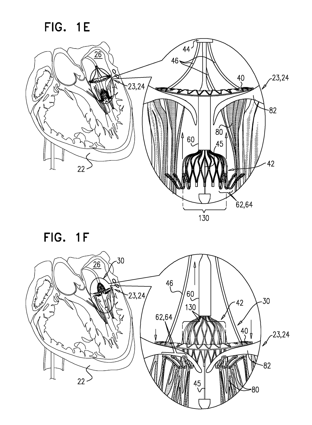
[0160]Reference is made to FIG. 1A-H, which are schematic illustrations of sequential steps in the implantation in a native heart valve 23 of the heart 22 of a subject 20 of an implant 30, comprising (1) a first prosthetic valve component, i.e., prosthetic valve support 40, and (2) a second prosthetic valve component, i.e., a prosthetic valve 42, in accordance with some applications of the present invention. For such applications of the present invention, native valve 23 includes a native mitral valve 24 by way of illustration and not limitation; the scope of the present invention includes implanting implant 30 in other valves of the heart (e.g., the tricuspid valve, the pulmonary valve, or the aortic valve). FIG. 1A illustrates a cross-section through heart 22 of the subject which is used throughout FIG. 1B-G to illustrate the implantation procedure. As shown in the cross-sectional illustration, native mitral valve 24 includes native leaflets 82, which are supported by native chord...
PUM
Abstract
Apparatus is provided for use with a native valve of a heart of a subject. The apparatus includes: (1) an annular upstream support portion, comprising an expandable first frame, the upstream support portion configured to be placed against an upstream surface of the native valve; (2) a flexible polyester connector; and (3) an anchoring element, flexibly coupled to the upstream support portion by the connector, and configured to anchor the upstream support portion to the native valve by engaging tissue of the native valve.
Description
CROSS-REFERENCES TO RELATED APPLICATIONS[0001]This application is a Continuation of U.S. Ser. No. 15 / 213,791 to Gross et al., filed Jul. 19, 2016, which published as US 2016 / 0324633, and which is a Continuation of U.S. Ser. No. 14 / 237,264 to Gross et al., filed May 23, 2014 (now abandoned), which published as US 2014 / 0324164, and which is the US National Phase of PCT Application IL2012 / 000292 to Gross et al., filed Aug. 5, 2012, which published as WO 2013 / 021374, and which[0002](1) claims priority from:[0003]U.S. 61 / 515,372 to Gross et al., filed Aug. 5, 2011;[0004]U.S. 61 / 525,281 to Gross et al., filed Aug. 19, 2011;[0005]U.S. 61 / 537,276 to Gross et al., filed Sep. 21, 2011;[0006]U.S. 61 / 555,160 to Gross et al., filed Nov. 3, 2011;[0007]U.S. 61 / 588,892 to Gross et al., filed Jan. 20, 2012; and[0008]U.S. Ser. No. 13 / 412,814 to Gross et al., filed Mar. 6, 2012, (now U.S. Pat. No. 8,852,272) all of which are incorporated herein by reference; and[0009](1) is a Continuation-In-Part of U...
Claims
Application Information
Patent Timeline
Application Date:The date an application was filed.
Publication Date:The date a patent or application was officially published.
First Publication Date:The earliest publication date of a patent with the same application number.
Issue Date:Publication date of the patent grant document.
PCT Entry Date:The Entry date of PCT National Phase.
Estimated Expiry Date:The statutory expiry date of a patent right according to the Patent Law, and it is the longest term of protection that the patent right can achieve without the termination of the patent right due to other reasons(Term extension factor has been taken into account ).
Invalid Date:Actual expiry date is based on effective date or publication date of legal transaction data of invalid patent.