

Topology optimization for subtractive manufacturing techniques
a subtractive manufacturing and topology optimization technology, applied in the field of computer science, can solve the problems of conventional design techniques conventional design techniques can generate geometries in the design solution that cannot be replicated or achieved, and achieve the effect of less post-processing and easy and direct manufacturing
- Summary
- Abstract
- Description
- Claims
- Application Information
AI Technical Summary
Benefits of technology
Problems solved by technology
Method used
Image

Examples
Embodiment Construction
[0003]Embodiments of the present invention generally relate to computer science and, more specifically, to topology optimization for subtractive manufacturing techniques.
[0004]Description of the Related Art
[0005]Subtractive manufacturing techniques are commonly used for manufacturing physical products that are designed through topology optimization. For example, these techniques are commonly used to manufacture metal-based products in the automotive and aerospace industries.
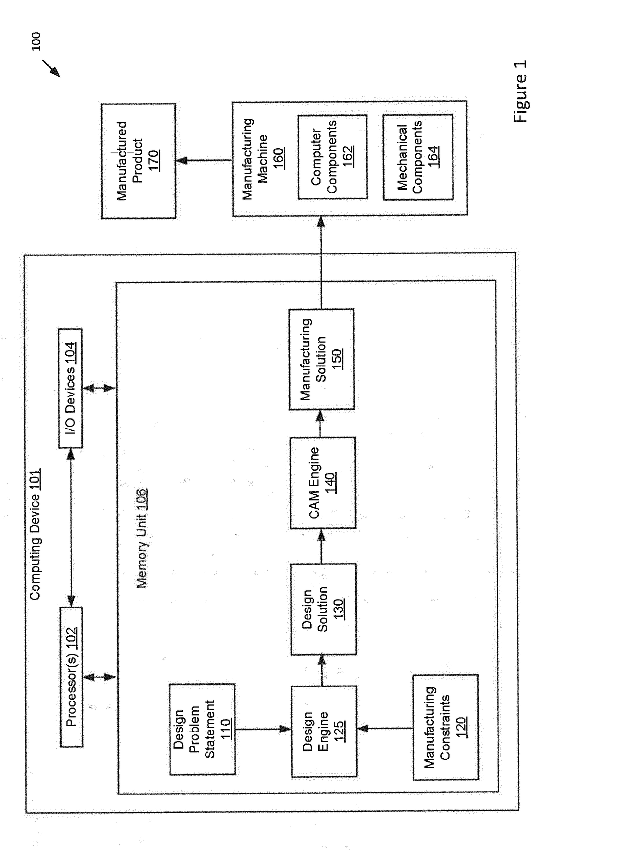
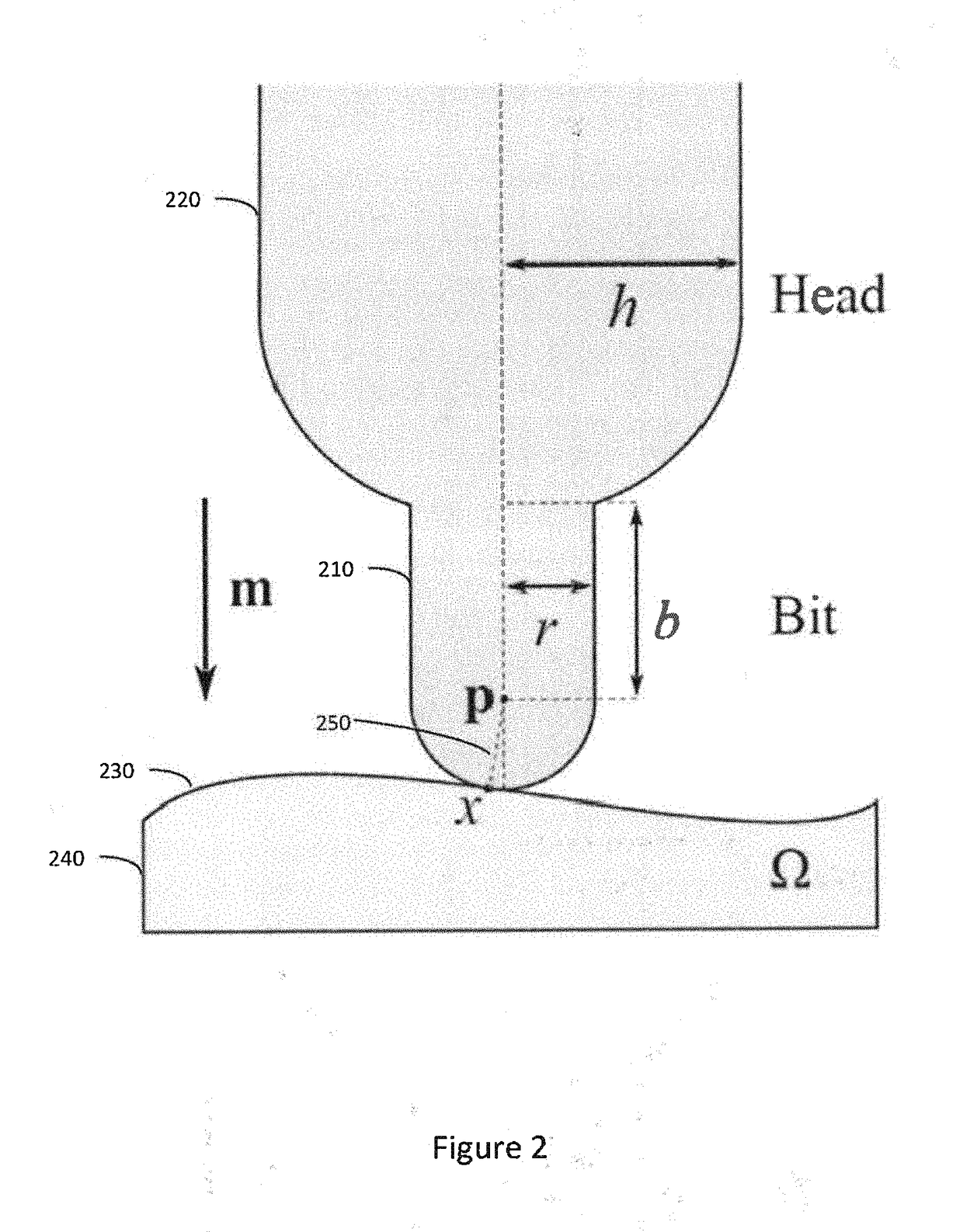
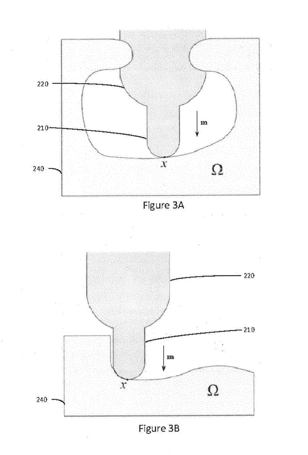
[0006]To manufacture a designed product using subtractive manufacturing techniques, a manufacturing machine, such as a computer numerical control (CNC) milling machine, begins with a solid block of material and gradually removes portions of material until the remaining material has a shape that resembles the designed product. A manufacturing machine may include a tool bit, tool head, and a table. The tool bit makes physical contact with the block of material to selectively remove material from the block. The tool...
PUM
 Abstract
Description
Claims
Application Information