
Two-stroke internal combustion engine with crankcase lubrication system

a technology of internal combustion engine and crankcase, which is applied in the direction of machines/engines, combustion-air/fuel-air treatment, automatic control of ignition, etc., can solve the problems of inefficiency in solving the problem of engine speed range, and achieve the effect of reducing engine noise, reducing engine noise, and reducing engine nois

Inactive Publication Date: 2018-12-06
MERCIER CESAR
View PDF0 Cites 4 Cited by
  • Summary
  • Abstract
  • Description
  • Claims
  • Application Information

AI Technical Summary

Benefits of technology

The present invention is a two-stroke engine with several technical effects. Firstly, it does not require an exhaust expansion chamber to prevent the fresh fuel and air mixture from leaving the combustion chamber. Secondly, it has a 360 degree oil pickup, allowing the engine to run with adequate lubrication in any position. Thirdly, it is easy to manufacturer with straight holes and simple shapes that can be mass produced without the need for sand mold casting. Fourthly, it uses screw-in intake valve to ease manufacturing, troubleshooting and repair. Fifthly, it has an intake valve near top dead center or cylinder head, and actuated by compressed air or fuel / air charge from a two-stroke rear compression chamber. The valve assembly is made of two chambers with a valve guide serves as a divider as well.

Problems solved by technology

Complex expansion chambers have helped to solve this problem, but the solution has not work efficiently across the speed range of the engine.

Method used


Image

  • Two-stroke internal combustion engine with crankcase lubrication system
  • Two-stroke internal combustion engine with crankcase lubrication system
  • Two-stroke internal combustion engine with crankcase lubrication system

Examples


Embodiment Construction

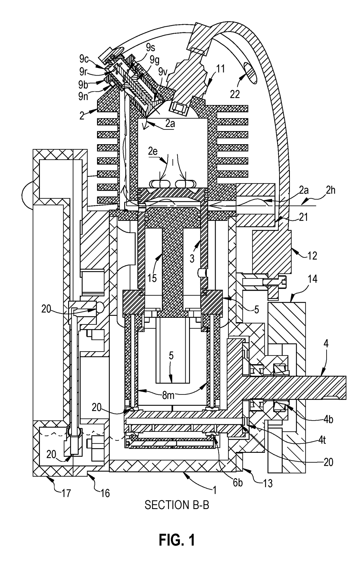
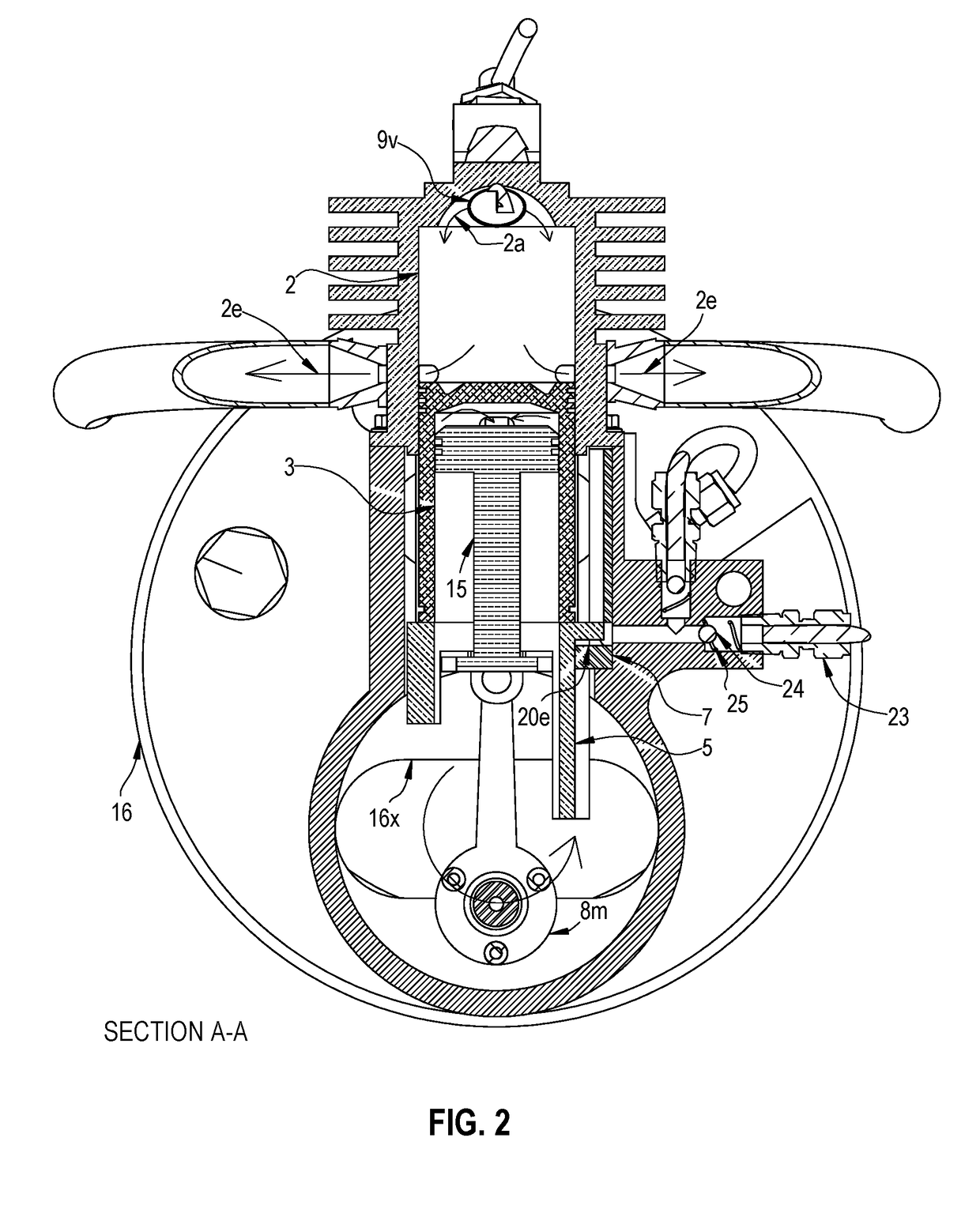
[0076]A cross section of a two-stroke single cylinder engine in accordance with the present invention is depicted in FIG. 1 and FIG. 2. The engine may be constructed with a plurality of cylinders as depicted in FIG. 8A.

[0077]Referring to FIG. 1, a piston 3 is movably mounted within a cylinder 2 forming a combustion chamber. A stationary piston 15 is adapted to function within the movable piston 3 forming a rear compression chamber. The stationary piston 15 is secured on cylinder 2 in this preferred embodiment as further shown in FIG. 5. Piston 15 may also be secured on the engine block or any other component that can provide adequate support. Piston 15 is used to create a sealed chamber with inlet bottom ports and outlet top ports on and underneath piston 3. A piston seat 5 is adapted to link the piston 3 to the piston rods 8m. The piston seat 5 is a multi-function component that is also used as part of an oil pump. Another function of seat 5 is to safely transfer reactive torque of...


PUM


Abstract

A two-cycle internal combustion engine with rear compression chamber, other than that of a crank case. This present engine has valves that can be screwed on the engine block near top dead center, and is actuated by air pressure. This present two-cycle engine yet uses an oil sump similar to that of a four-cycle engine, which eliminating the need to premix oil with the fuel. This present engine has a stationary piston which operates within a movable piston to form a rear-compression chamber. The movable piston has ports near its crown to transfer charge to the combustion chamber. The movable piston also has ports near bottom of its skirt to allow the fuel and air mixture to enter the rear compression chamber. This engine has a piston seat which is adapted to connect the movable piston to the connecting rod.

Description

RELATED APPLICATION[0001]This patent application is related to U.S. Provisional Patent Application No. 62 / 182,165 filed by applicant Cesar Mercier on Jun. 19, 2015, and claims the benefit of that filing date.BACKGROUND OF THE INVENTION[0002]A conventional two-stroke engine requires oil to be premixed with the fuel in order to lubricate moving components of the engine. The crankcase has to be sealed as a result. This prevents a two-stroke engine from sharing a crankcase. U.S. Pat. No. 4,450,794 and U.S. Pat. No. 4,791,892, titled “Two-stroke engine”, filed by Roger M. Hall, are good examples of this problem.[0003]A conventional two-stroke engine has transfer ports near bottom dead center which causes some of the fuel to exit the combustion chamber with the exhaust. Complex expansion chambers have helped to solve this problem, but the solution has not work efficiently across the speed range of the engine.[0004]A conventional two-stroke engine has a long piston skirt which often brushe...

Claims


Application Information

Patent Timeline
Patent Type & Authority Applications(United States)
IPC IPC(8): F01M1/02F02P5/06F02P3/02F02M35/10F02B75/32F02B75/02F01M11/00
CPCF01M1/02F02P5/06F02P3/02F02M35/10255F02B2075/025F02B75/02F01M11/0004F01M2001/0238F01M2011/007F02B75/32F02B33/12F02B33/16F01B7/20F02B75/30F01M11/065F02P1/02
Inventor MERCIER, CESAR
Owner MERCIER CESAR
Learn More