Lc composite component

a composite component and composite technology, applied in the direction of fixed capacitor details, transformer/react mounting/support/suspension, fixed capacitors, etc., can solve the problem that the resonance point cannot be formed on the low frequency side, and achieve the effect of reducing the interference between the magnetic flux of the coil and the mounting board, suppressing the reduction of the q-value of the coil, and reducing the loss of the coil

Active Publication Date: 2018-12-06
MURATA MFG CO LTD
View PDF1 Cites 3 Cited by
  • Summary
  • Abstract
  • Description
  • Claims
  • Application Information

AI Technical Summary

Benefits of technology

[0006]In this regard, it is conceivable that the area of the capacitor conductor layer is increased by forming the coil conductor layer on a layer different from the capacitor conductor layer. However, as the area of the capacitor conductor layer becomes larger, an overlap with the coil conductor layer becomes greater and the magnetic flux generated in the coil conductor layer is blocked by the capacitor conductor layer, so that an acquisition efficiency of the L-value of the coil decreases. As a result, the Q-value of the coil is reduced, and an intended filter characteristic may not be acquired due to a decrease in resonance peak and a broadening of bandwidth.
[0021]According to the LC composite component of one embodiment of the present disclosure, the resonance point can be formed on the lower frequency side while suppressing a reduction in the Q-value of the coil.

Problems solved by technology

The inventor of the present application found that the following problem exists when the conventional coil component as described above is actually manufactured and used.
Therefore, the acquirable capacitance of the capacitor conductor layer becomes small, so that a resonance point cannot be formed on the low frequency side.

Method used


Image

  • Lc composite component
  • Lc composite component
  • Lc composite component

Examples


first embodiment

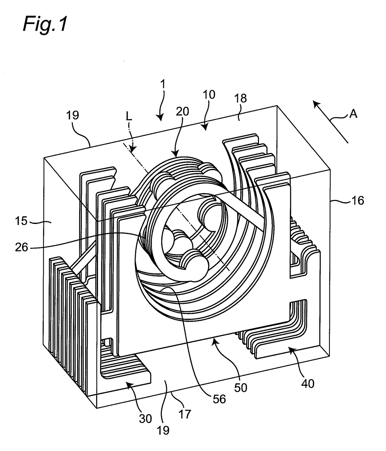
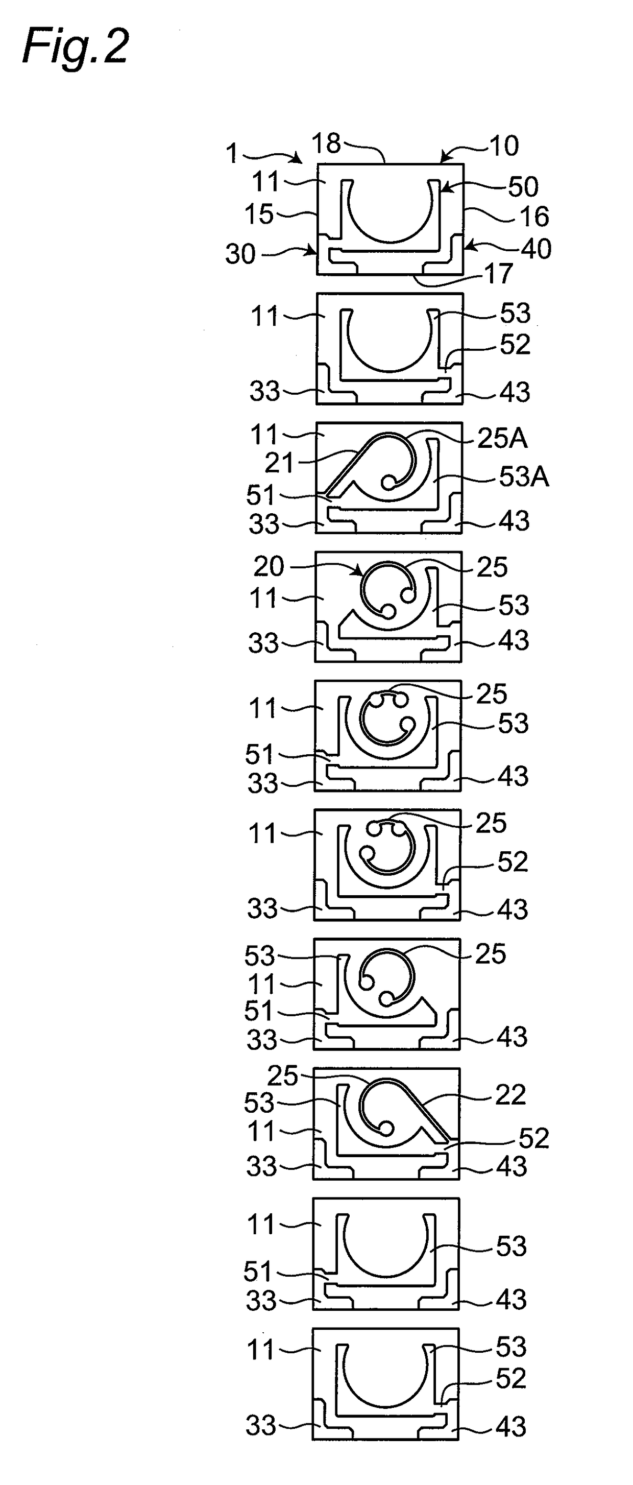
[0029]FIG. 1 is a transparent perspective view of a first embodiment of an LC composite component. FIG. 2 is an exploded plane view of the LC composite component. As shown in FIGS. 1 and 2, an LC composite component 1 includes an element body 10, a coil 20 disposed in the element body 10, a capacitor 50 disposed in the element body 10, and a first external electrode 30 and a second external electrode 40 disposed in the element body 10. Although depicted as being transparent in FIG. 1 so that a structure can easily be understood, the element body 10 may be semitransparent or opaque or may be colored.

[0030]A first end of the coil 20 is connected to the first external electrode 30, and a second end of the coil 20 is connected to the second external electrode 40. The capacitor 50 is electrically connected in parallel to the coil 20. The LC composite component 1 constitutes an LC parallel resonator. The coil 20 and the capacitor 50 are electrically connected through the first and second ...

second embodiment

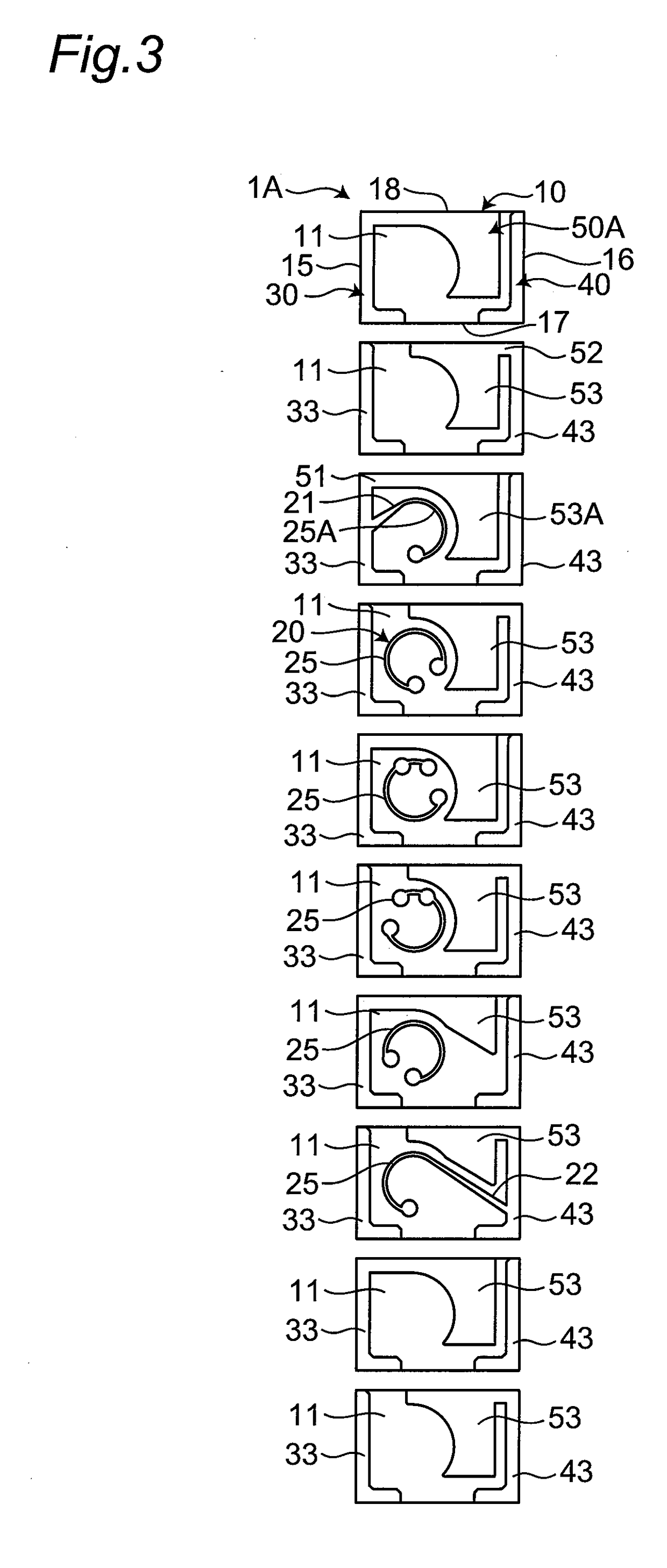
[0049]FIG. 3 is an exploded plane view of a second embodiment of the LC composite component. The second embodiment is different from the first embodiment in the positions of the capacitor. This different configuration will hereinafter be described. In the second embodiment, the same constituent elements as the first embodiment are denoted by the same reference numerals as the first embodiment and therefore will not be described.

[0050]As shown in FIG. 3, an LC composite component 1A of the second embodiment has a capacitor 50A disposed between the coil 20 and two sides (the second end surface 16 and the top surface 18) of the element body 10. The first external electrode 30 extends from the bottom surface 17 to the top surface 18 of the first end surface 15 of the element body 10 and the second external electrode 40 extends from the bottom surface 17 to the top surface 18 of the second end surface 16 of the element body 10. Therefore, the coil 20 is located on the first external elec...

experimental example

[0059]Results of simulation with the first embodiment (FIG. 1), a first comparative example, and a second comparative example will be described.

[0060]As shown in FIG. 4A, an LC composite component 100A of the first comparative example is an LC composite component as described in Japanese Laid-Open Patent Publication No. 2001-134732. A capacitor 150A is disposed between the bottom surface 17 of the element body 10 and the coil 20 when viewed in the direction of the axis L of the coil 20.

[0061]As shown in FIG. 4B, an LC composite component 100B of the second comparative example is an LC composite component as described in Japanese Laid-Open Patent Publication No. 2005-184127. A capacitor 150B is disposed at a position overlapping an inner diameter portion (the axis L of the coil 20) of the coil 20.

[0062]In FIGS. 4A and 4B, the same constituent elements as the first embodiment are denoted by the same reference numerals as the first embodiment (FIG. 1) and therefore will not be describe...


PUM

PropertyMeasurementUnit
lengthaaaaaaaaaa
lengthaaaaaaaaaa
lengthaaaaaaaaaa

Abstract

An LC composite component comprising an element body, a helically wound coil disposed in the element body, and a capacitor disposed on an outer circumferential side of the coil in the element body. When viewed in an axial direction of the coil, the element body is rectangular, and the capacitor is disposed between at least two sides of the element body and the coil.

Description

CROSS REFERENCE TO RELATED APPLICATION[0001]This application claims benefit of priority to Japanese Patent Application 2017-111944, filed Jun. 6, 2017, the entire content of which is incorporated herein by reference.BACKGROUNDTechnical Field[0002]The present disclosure relates to an LC composite component.Background Art[0003]A conventional LC composite component is described in Japanese Laid-Open Patent Publication No. 2001-134732. This LC composite component has a rectangular parallelepiped sheet body, a helical coil conductor layer disposed in the sheet body, and a capacitor conductor layer disposed in the sheet body. The coil conductor layer and the capacitor conductor layer are disposed on the same layer. When viewed in an axial direction of the coil conductor layer, the capacitor conductor layer is disposed between one side of the sheet body and a coil.SUMMARY[0004]The inventor of the present application found that the following problem exists when the conventional coil compone...

Claims


Application Information

Patent Timeline
Patent Type & Authority Applications(United States)
IPC IPC(8): H03H1/00H01G4/30H01F27/29H01G4/40H01F27/06H01F27/40H01G4/232
CPCH01F27/40H01G4/232H03H2001/0078H01F27/06H03H2001/0085H01G4/30H01F27/29H01G4/40H03H1/00H01F17/0006H01F27/2804H01F27/292H01F27/323H01F2017/0073H01F2027/2809H01G4/005H01G4/385H03H2001/005H01F17/0013H01F2017/0026H01G2/02H03H7/0115H01G4/228
Inventor MIYOSHI, HIROMI
Owner MURATA MFG CO LTD
Why Eureka
Try Eureka