

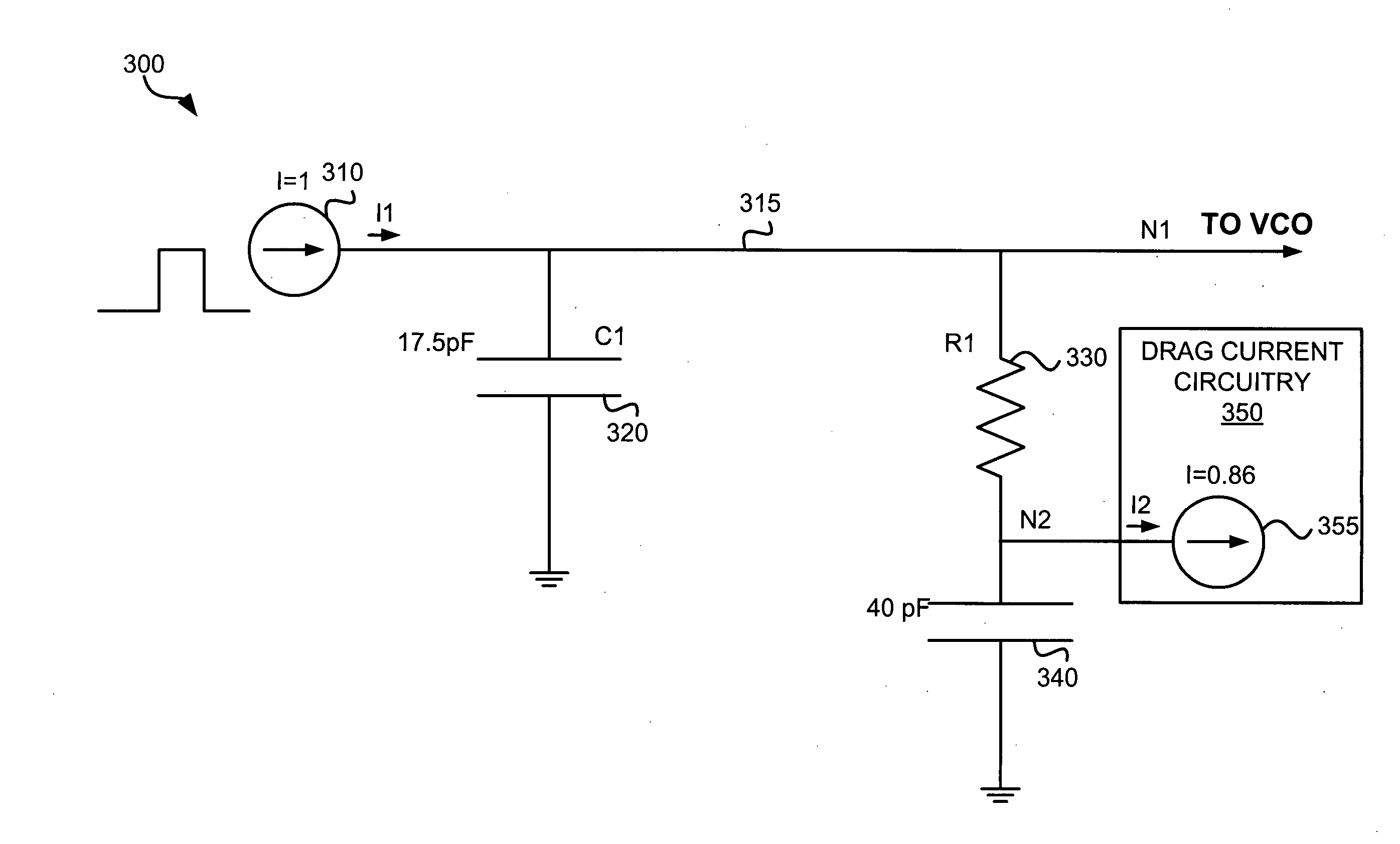
Phase-locked loop filter capacitance with a drag current
a phase-locked loop and capacitance technology, applied in pulse automatic control, electric devices, etc., can solve the problems of increasing the overall size of the pll, increasing the noise contribution, increasing the difficulty of implementation, etc., and achieves the effect of reducing the loop bandwidth, increasing the capacitor area, and being easy to manag
- Summary
- Abstract
- Description
- Claims
- Application Information
AI Technical Summary
Benefits of technology
Problems solved by technology
Method used
Image

Examples
Embodiment Construction
[0024] The embodiments discussed herein are illustrative of examples of the present invention. As these embodiments of the present invention are described with reference to illustrations, various modifications or adaptations of the methods and / or specific structures described may become apparent to those skilled in the art. All such modifications, adaptations, or variations that rely upon the teachings of the present invention, and through which these teachings have advanced the art, are considered to be within the scope of the present invention. Hence, these descriptions and drawings should not be considered in a limiting sense, as it is understood that the present invention is in no way limited to only the embodiments illustrated.
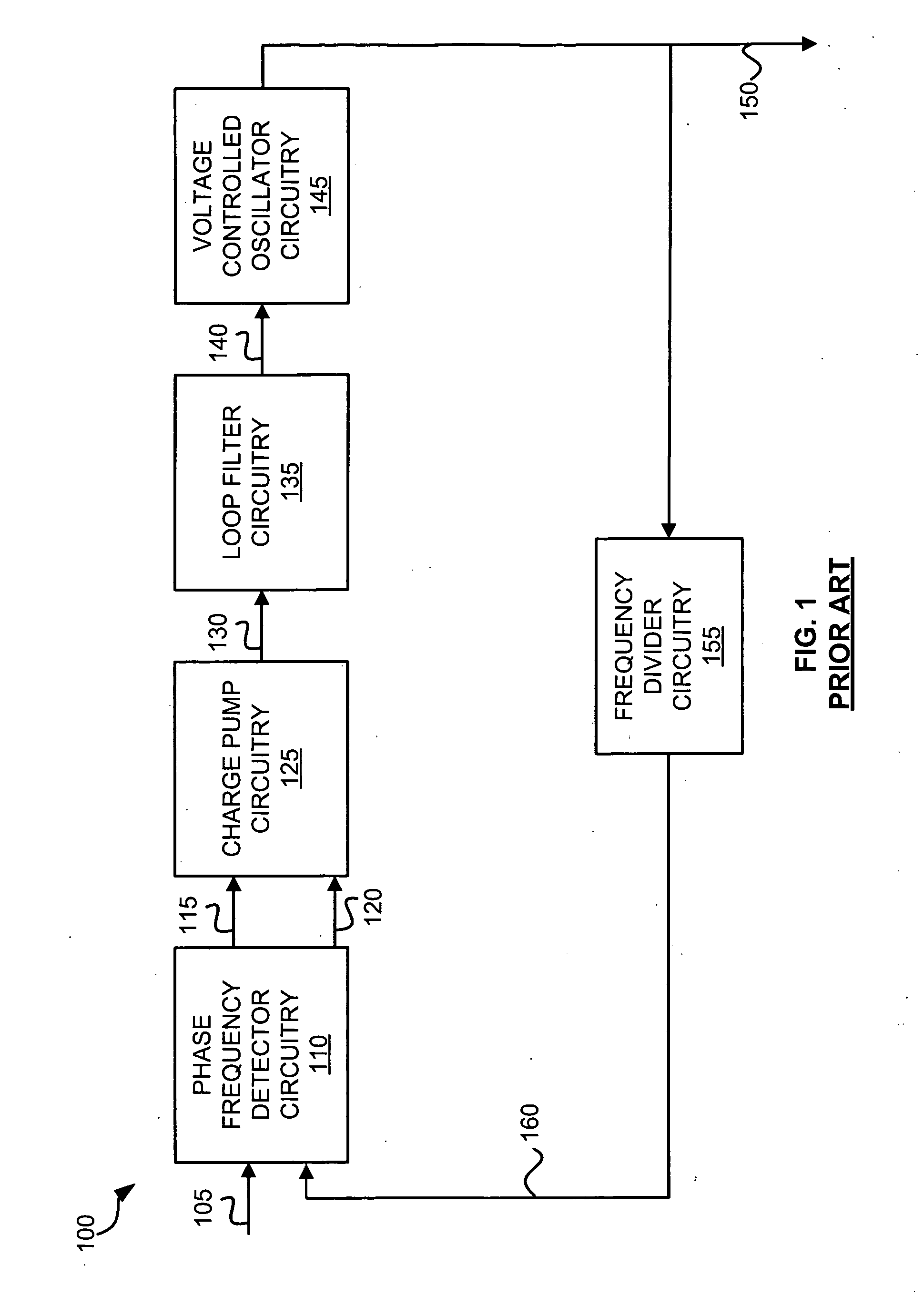
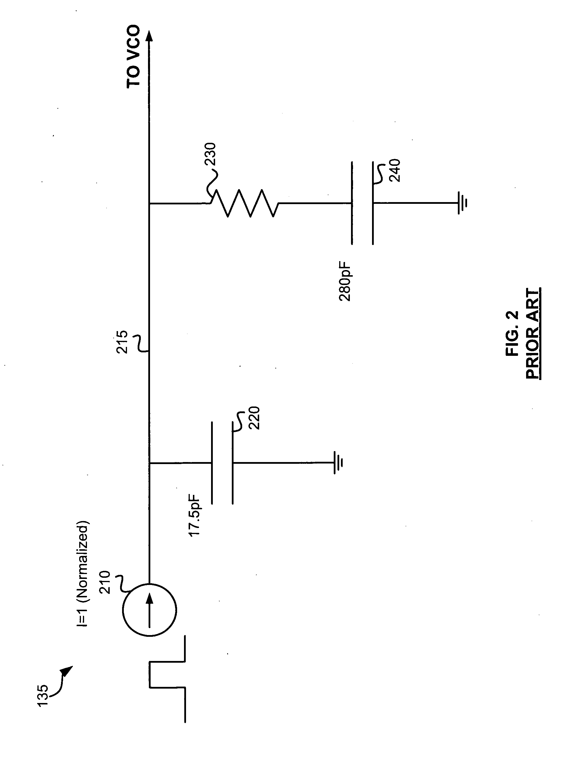
[0025] The embodiments discussed herein are described in the context of phase-locked loop circuitry. However, other embodiments of the invention may be implemented in any circuit that implements “an integration function”, which can reduce the size of the...
PUM
 Abstract
Description
Claims
Application Information