Optical-to-electrical converter unit and semiconductor light-receiving device
a technology of optical-to-electrical converter and semiconductor light-receiving device, which is applied in the direction of optics, optical elements, instruments, etc., can solve the problem that the semiconductor light-receiving device is difficult to operate stably, and achieve the effect of reducing the parametric capacitance generated between the back electrode and the semiconductor layer
- Summary
- Abstract
- Description
- Claims
- Application Information
AI Technical Summary
Benefits of technology
Problems solved by technology
Method used
Image
Examples
example 1
, and
[0039]FIG. 21 is a circuit diagram showing electrical connections in a semiconductor light-receiving device according to Comparative Example.
DESCRIPTION OF THE PREFERRED EMBODIMENTS
[0040]Embodiments for carrying out the present invention will now be described in detail with reference to the attached drawings. In the description of the drawings, the same elements are represented by the same reference characters and the descriptions therefor are omitted to avoid redundancy.
first embodiment
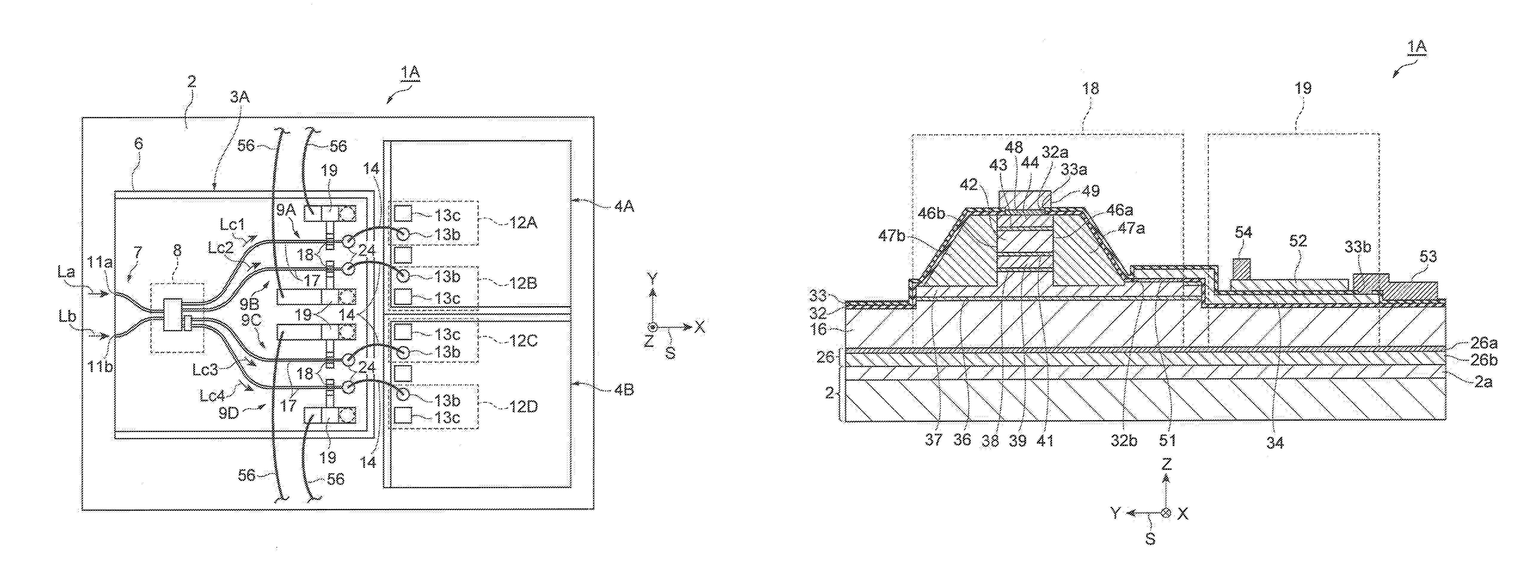
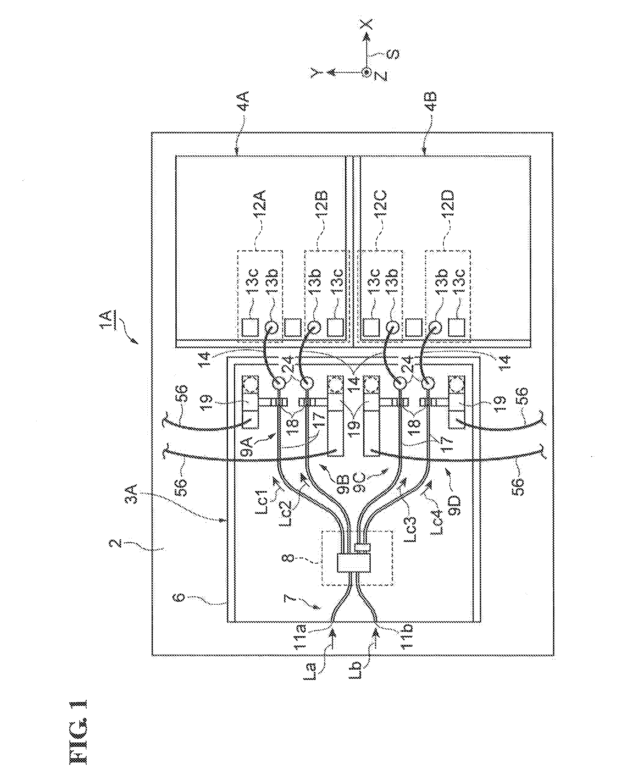
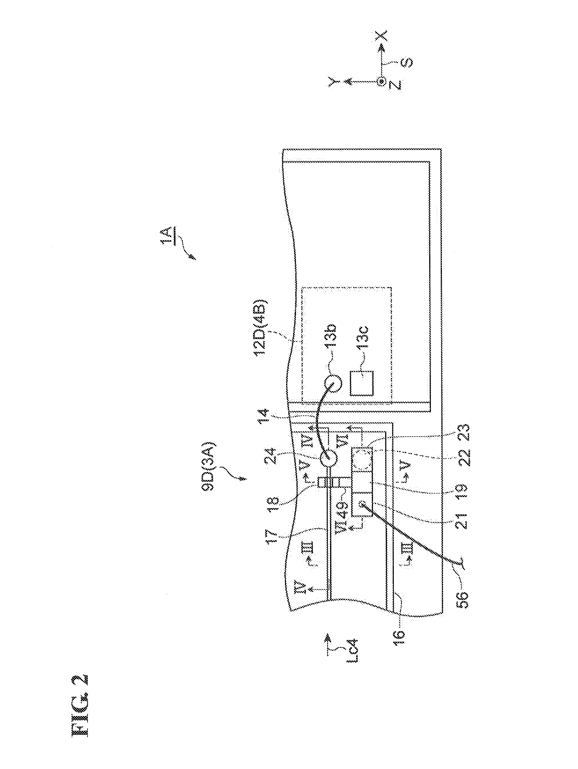
[0041]An optical waveguide-type semiconductor light-receiving device (hereinafter may be simply referred to as “light-receiving device”) according to a first embodiment is described with reference to FIGS. 1 to 7. FIG. 1 is a plan view of an optical waveguide-type semiconductor light-receiving device according to a first embodiment. FIG. 2 is a partial enlarged view of the semiconductor light-receiving device according to the first embodiment. FIG. 3 is a cross-sectional view taken along line III-III in FIG. 2. FIG. 4 is a cross-sectional view taken along line IV-IV in FIG. 2. FIG. 5 is a cross-sectional view taken along line V-V in FIG. 2. FIG. 6 is a cross-sectional view taken along line VI-VI in FIG. 2. FIG. 7 is a circuit diagram showing electrical connections in the semiconductor light-receiving device according to the first embodiment. For the sake of convenience, an orthogonal coordinate system S is included in each drawing.
[0042]In recent years, optical communication systems...
second embodiment
[0086]An optical waveguide-type semiconductor light-receiving device 1B according to a second embodiment will now be described with reference to FIGS. 13 and 14. FIG. 13 is a cross-sectional view of the semiconductor light-receiving device 1B. The cross section (XZ plane) of the O / E converter 9D taken in the waveguiding direction (X direction) is shown in FIG. 13. FIG. 14 is a cross-sectional view of the semiconductor light-receiving device 1B. The cross section (YZ plane) of the O / E converter 9D perpendicular to the waveguiding direction (X direction) is shown in FIG. 14. The semiconductor light-receiving device 1B differs from the light-receiving device 1A in that it has a back electrode 26B having a structure different from that of the back electrode 26 of the light-receiving device 1A. In particular, the back electrode 26 of the light-receiving device 1A is formed over the entire back surface 16b of the substrate 16. In contrast, the back electrode 26B of the semiconductor light...
PUM
 Abstract
Description
Claims
Application Information
 - R&D
- Intellectual Property
- Life Sciences
- Materials
- Tech Scout
- Unparalleled Data Quality
- Higher Quality Content
- 60% Fewer Hallucinations
Browse by: Latest US Patents, China's latest patents, Technical Efficacy Thesaurus, Application Domain, Technology Topic, Popular Technical Reports.
© 2025 PatSnap. All rights reserved.Legal|Privacy policy|Modern Slavery Act Transparency Statement|Sitemap|About US| Contact US: help@patsnap.com


