
Organic flow cell batteries and materials for use in same

Active Publication Date: 2018-12-13
CAMBRIDGE DISPLAY TECH LTD
View PDF3 Cites 5 Cited by
  • Summary
  • Abstract
  • Description
  • Claims
  • Application Information

AI Technical Summary

Benefits of technology

The present invention is about an organic flow cell battery that uses an organic molecule as both the positive and negative electroactive redox material. This design allows for two-electron processes to occur in a single molecule, resulting in a total of four-electron transitions. This design reduces material costs and allows for equal ease of charging in either direction.

Problems solved by technology

The wide-scale utilization of flow batteries is presently limited by the availability and cost of the redox materials, in particular those that are based on redox-active transition metals such as vanadium, and / or require precious-metal electrocatalysts.
However, the toxicity of inorganic redox materials such as vanadium salts or bromine limits the applicability of flow batteries for energy storage in the context of distributed, modular energy generation technologies that use (intermittent) “green power” such as wind, photovoltaic, or hydroelectric power.
This can also be done with organic molecules through the use of stabilised radicals, but in general organic radicals are either relatively chemically reactive or require so much stabilisation that it is difficult to generate the high redox potentials required for a significant cell voltage.
While single-electron transfer materials (e.g. triazine) have been considered, they involve limitations in that they only comprise one electron per molecule.
However, this process makes it difficult to produce high cell potentials due to the relative similarity of the compounds—within one class it is unlikely that both the oxidised form of one and the reduced form of the other will have high reactivity.
However, leakage of the redox materials through the separator membrane has been identified as being a cause of device degradation, as the available volume of redox active material is slowly reduced and there is also the potential for unwanted reactions to occur between the different redox active materials.

Method used


Image

  • Organic flow cell batteries and materials for use in same
  • Organic flow cell batteries and materials for use in same
  • Organic flow cell batteries and materials for use in same

Examples


Embodiment Construction

[0022]For a more complete understanding of the present invention, reference is now made to the following description:

[0023]The present invention has been made upon studying two-electron processes which prevent the necessity of forming unpaired electrons (radicals) in organic molecules, and can readily be accommodated by changing the α- and π-bonds into a different oxidation state and can therefore be advantageous for enhancing both the stability and the cell potential of a battery system.

[0024]One requirement of any battery system is for an ion to pass through the separating membrane to compensate for the electron movement through the external circuit. Ions can be positive or negative, but some of the most common include H+, Li+, Na+, Mg2+. Coordination of these ions can be used to stabilise the organic molecules, particularly in their reduced states. This is particularly helped when atoms that enhance this coordination are available—typical atoms include O, N, S but can also includ...


PUM


Abstract

The present invention relates to an organic flow cell battery having a material comprising an organic molecule that can be used as the electroactive redox material for both electrodes of the battery. By enabling two-electron processes both of the oxidation and reduction to occur in a single molecule, a total of 4-electron transitions is achieved, which allows the organic molecule to be used on both sides of the separator, reducing material costs and allowing the battery to be charge in either direction with equal ease.

Description

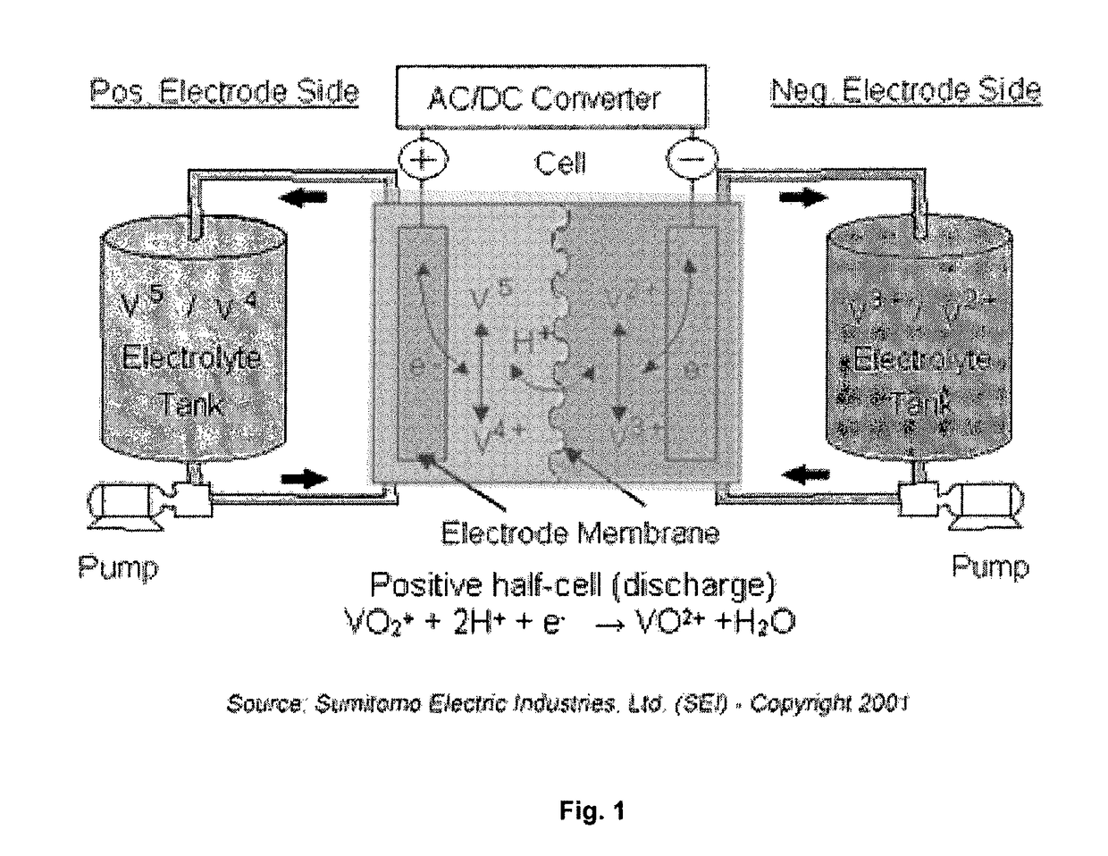
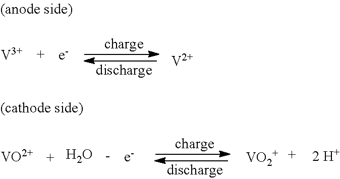
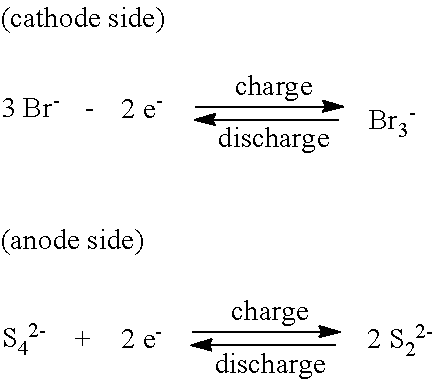
FIELD OF INVENTION[0001]The present invention relates to organic flow cell batteries and materials for use in organic flow cell batteries. In particular the invention provides examples of organic redox materials for use in flow cell batteries as substitutes for toxic and / or expensive inorganic redox materials such as vanadium salts or bromine.BACKGROUND OF THE INVENTION[0002]Redox flow cells are secondary batteries in which all electrochemical components are dissolved in the electrolyte.[0003]The energy capacity of the redox flow cell is independent of its power, as the energy available only depends on the electrolyte volume (amount of liquid electrolyte), whereas the power depends on the surface area of the electrodes.[0004]A well-established example is the vanadium redox flow battery, which contains redox couples entirely based on vanadium cations (see FIG. 1). Typical performance data are shown in Tab. 1:TABLE 1Vanadium redox battery performance.Specific Energy10-20 Wh / kg (36-72 ...

Claims


Application Information

Patent Timeline
IPC IPC(8): H01M4/60H01M8/18H01M4/36H01M8/0239
CPCH01M4/60H01M8/188H01M4/368H01M8/0239C07D209/04C07D209/36Y02E60/50Y02E60/10
Inventor PILLOW, JONATHAN
Owner CAMBRIDGE DISPLAY TECH LTD
Learn More