Fet driving circuit

a driving circuit and transistor technology, applied in the direction of power conversion systems, oscillation generators, pulse techniques, etc., can solve the problems of increasing circuitry cost, complex design, switching frequency fluctuation, etc., and achieve low withstand voltage, low voltage, and optimized impedance characteristics

Active Publication Date: 2018-12-27
TDK CORPARATION
View PDF3 Cites 2 Cited by
  • Summary
  • Abstract
  • Description
  • Claims
  • Application Information

AI Technical Summary

Benefits of technology

[0017]According to the present invention, it is possible, by repeatedly switching a switch on and off in a FET driving circuit equipped with an LC resonance circuit with impedance characteristics including four resonant frequencies (a first resonant frequency to a fourth resonant frequency), to output a driving voltage for driving the FET to be driven across the output terminals. Here, by using an LC resonance circuit with optimized impedance characteristics, it is possible to attenuate a second harmonic component and a fourth harmonic component of a switching frequency in the voltage applied across both ends of the switch when the switch is off, and by doing so, it is possible to produce a waveform that is closer to a rectangular waveform. In this way, with this FET driving circuit, since it is possible to lower the voltage applied across both ends of the switch, it is possible to use a switch with a low withstand voltage and therefore a low on-resistance, which makes it possible to reduce the loss (conduction loss) of the driving circuit itself. At the same time, since it is possible to reduce the peak value of the gate driving voltage of the FET to be driven, it is possible to maintain a low derating for the gate voltage of the FET to be driven, which makes it possible to improve the reliability of the FET. Also, according to this FET driving circuit, it is possible to significantly shorten the time taken by the voltage applied across both ends of the switch to rise and fall (i.e., to significantly steepen the voltage gradients of rises and falls), which makes it possible to significantly reduce the switching loss of the driving circuit itself. At the same time, it is possible to significantly shorten the time taken by the gate driving voltage of the FET to be driven to rise and fall (i.e., to significantly steepen the voltage gradients of rises and falls), which makes it possible to significantly reduce the switching loss and conduction loss at the FET. Also, according to this FET driving circuit, it is possible to reduce the driving loss due to current resonance between the input inductance and the input capacitance, which is the gate-source characteristics of a FET. Since a single switch is sufficient in this FET driving circuit, compared to a configuration that uses a larger number of switches, it is possible to avoid an increase in the cost of components, an increase in the mounting cost of components, and an increase in the mounting area of components, and to also realize a simplified circuit. Since no dead time is set to prevent cross conduction, it is also possible to drive the FET at even higher frequencies. Since an externally excited configuration is used, it is also possible to avoid fluctuations in the switching frequency. According to this FET driving circuit, since the amplitude of the voltage to drive the FET depends on the DC input voltage, by adjusting the DC input voltage, it is possible to freely adjust the amplitude of the voltage. In particular, when switching operations are performed at high frequency, various adverse effects will occur if the wiring paths of the patterns on which the high-frequency switching current flows are long. However, with a FET driving circuit that includes an LC resonance circuit with the impedance characteristics described above, it is easy to make the wiring paths extremely short and suppress the effects of noise, such as components being affected by noise or conversely emitting noise. By integrating the components, it is possible to suppress differences in the fluctuations in element characteristics, which contributes to making operations more stable. It is also possible to reduce the manufacturing cost, to miniaturize the device, and optimize the operation of the device.

Problems solved by technology

However, since the FET driving circuit in Non-Patent Literature 1 described above is self-excited, there is the problem that the design is complex and a further problem in that the switching frequency fluctuates.
On the other hand, although the FET driving circuit according to Patent Literature 1 mentioned above is externally excited and therefore does not have the problems with the FET driving circuit according to Non-Patent Literature 1 described above (the problems of being complex to design and the switching frequency fluctuating), the FET driving circuit according to Patent Literature 1 requires four switches, which increases the cost of circuitry and since dead time needs to be set to prevent cross conduction, it is difficult to increase the operating frequency.

Method used


Image

  • Fet driving circuit
  • Fet driving circuit
  • Fet driving circuit

Examples


Embodiment Construction

[0028]Several preferred embodiments of the present invention will now be described. Note that the present invention is not limited to the following embodiments. The component elements described below include equivalent component elements that should be apparent to those of skill in the art, and such component elements may be combined as appropriate.

[0029]The embodiments of the present invention will now be described in detail with reference to the drawings. Note that in the description of the drawings, elements that are the same have been assigned the same reference numerals and duplicated description thereof is omitted.

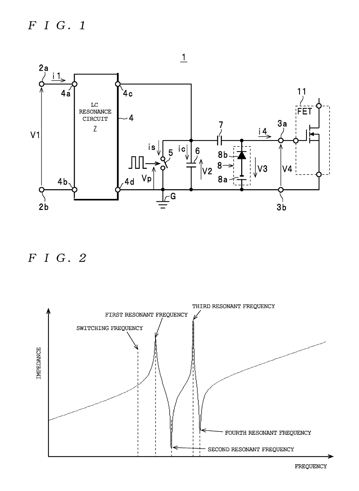
[0030]First, the configuration of a FET driving circuit 1 as one example of a FET driving circuit will be described with reference to FIG. 1.

[0031]The FET driving circuit 1 includes a pair of direct current (DC) input terminals 2a and 2b (hereinafter collectively referred to as the “DC input terminals 2” when no distinction is made), a pair of output terminals 3a and...


PUM


Abstract

A FET driving circuit includes: two inputs for inputting a DC voltage; two outputs respectively connected to gate and source electrodes of a FET; a switch; a resonant capacitance connected between both ends of the switch; and an LC resonance circuit connected between the inputs and both ends of the switch. When the two inputs are shorted, frequency characteristics of an impedance of the LC resonance circuit include, in order from a low to a high-frequency side, first to fourth resonant frequencies. The first resonant frequency is higher than a switching frequency of the switch, the second resonant frequency is around double the switching frequency, the fourth resonant frequency is around four times the switching frequency, and the impedance has local maxima at the first resonant frequency and the third resonant frequency and local minima at the second resonant frequency and the fourth resonant frequency.

Description

FIELD OF THE INVENTION[0001]The present invention relates to a FET (Field Effect Transistor) driving circuit that drives a FET used as a switching element, such as a converter, an inverter, or a switching power supply.DESCRIPTION OF THE RELATED ART[0002]A resonant FET driving circuit is well known as a FET driving circuit for driving a FET (for example, a MOSFET) at a high switching frequency (see Non-Patent Literature 1 (Very-High-Frequency Resonant Boost Converters, IEEE TRANSACTIONS ON POWER ELECTRONICS, VOL. 24, NO. 6, JUNE 2009, PP 1654-1665) and Patent Literature 1 (Japanese Translation of PCT International Publication No. 2007-501544)).[0003]Non-Patent Literature 1 discloses a self-excited FET driving circuit which, as depicted in FIG. 5 of the cited document, includes a switch element (MOSFET) connected between the gate electrode and the source electrode of the FET to be driven and an LC resonance circuit that is connected to the gate electrode of the FET to be driven and fu...

Claims


Application Information

Patent Timeline
Patent Type & Authority Applications(United States)
IPC IPC(8): H03K17/0412H03K17/0416H02M1/38
CPCH03K17/04123H03K17/04163H02M1/38H03K2217/009H03K2217/0036H03B5/1203
Inventor LIN, MINMATSUURA, KEN
Owner TDK CORPARATION
Why Eureka
Try Eureka