Coil component and circuit board including the same

Active Publication Date: 2019-01-03
TDK CORPARATION
View PDF3 Cites 4 Cited by
  • Summary
  • Abstract
  • Description
  • Claims
  • Application Information

AI Technical Summary

Benefits of technology

[0010]According to the present invention, leakage magnetic flux from the coil component is reduced, enabling high density mounting on the mounting substrate.
[0011]In the present invention, the mounting substrate preferably has a ground pattern formed so as to overlap the coil component. With this configuration, leakage magnetic flux to the first high permeability part is shielded by the ground pattern, allowing further reduction in

Problems solved by technology

However, reduction in the size of the coil component involves reduction in the volume of a magnetic member constituting the coil component, with the result that magnetic flux is more likely to leak outside.
However, in recent years, a coil component is required to have a s

Method used


Image

  • Coil component and circuit board including the same
  • Coil component and circuit board including the same
  • Coil component and circuit board including the same

Examples


first embodiment

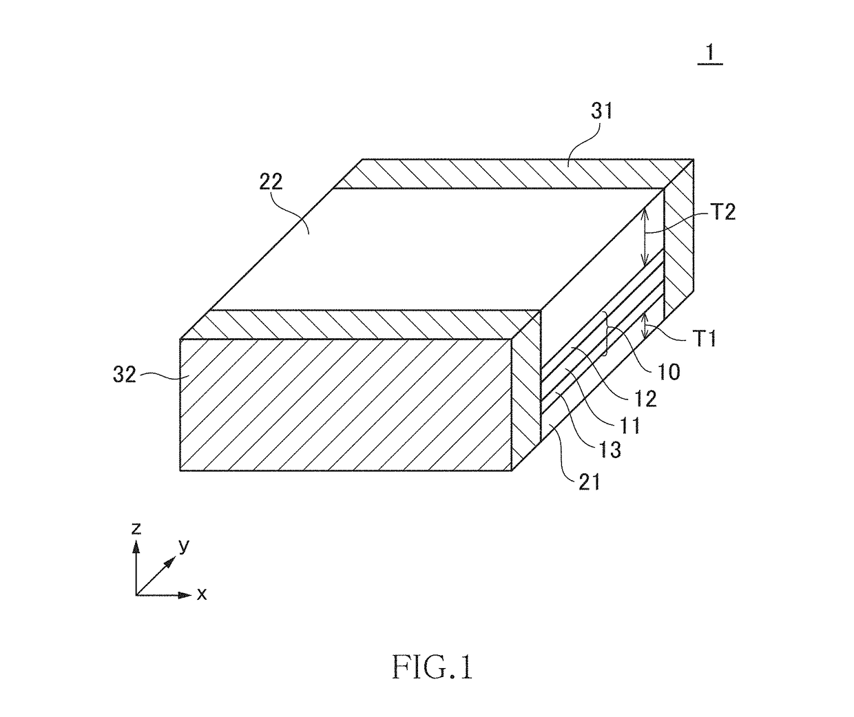
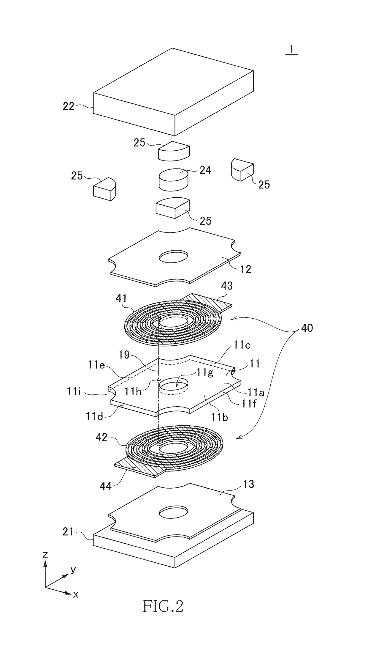
[0022]FIG. 1 is a schematic perspective view illustrating the outer shape of a coil component 1 according to the first embodiment of the present invention.

[0023]As illustrated in FIG. 1, the coil component 1 according to the present embodiment is a surface-mount type chip component and has a coil layer 10 and first and second magnetic layers 21 and 22 provided on both sides of the coil layer 10 in the illustrated z-direction. The coil component 1 has a substantially rectangular parallelepiped outer shape, and first and second terminal electrodes 31 and 32 are provided on both sides thereof in the illustrated y-direction. The first and second terminal electrodes 31 and 32 are formed not only on the illustrated xz plane, but also on the xy and yz planes. Particularly, on the xy plane, the first and second terminal electrodes 31 and 32 are formed on both the xy plane constituted by the first magnetic layer 21 and xy plane constituted by the second magnetic layer 22. In the coil compone...

second embodiment

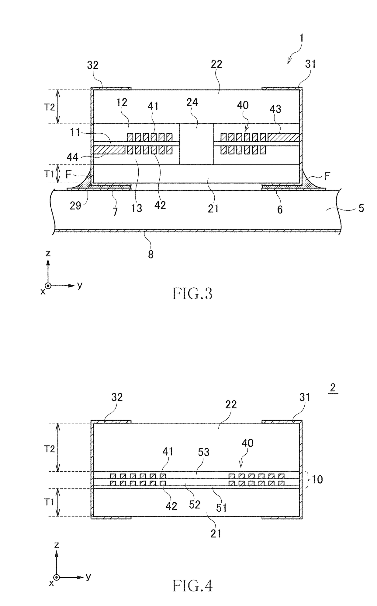
[0043]FIG. 4 is a cross-sectional view for explaining the structure of a coil component 2 according to the second embodiment of the present invention.

[0044]As illustrated in FIG. 4, the coil component 2 according to the present embodiment has a configuration in which the coil layer 10 is arranged on the surface of the first magnetic layer 21 in a stacked manner. Specifically, insulating resin layers 51 to 53 are stacked in this order on the surface of the first magnetic layer 21, a spiral conductor 42 is formed between the insulating resin layers 51 and 52, and a spiral conductor 41 is formed between the insulating resin layers 52 and 53. Other configurations are basically the same as those in the coil component 1 according to the first embodiment, so the same reference numerals are given to the same elements, and overlapping description will be omitted.

[0045]In the manufacturing process of the coil component 2, first, the first magnetic layer 21 is prepared, and then the insulating...

third embodiment

[0047]FIG. 5 is a cross-sectional view for explaining the structure of a coil component 3 according to the third embodiment of the present invention.

[0048]As illustrated in FIG. 5, the coil component 3 according to the present embodiment has a configuration in which the coil layer 10 is arranged on the surface of the second magnetic layer 22 in a stacked manner. Specifically, insulating resin layers 61 to 63 are stacked in this order on the surface of the second magnetic layer 22, a spiral conductor 41 is formed between the insulating resin layers 61 and 62, and a spiral conductor 42 is formed between the insulating resin layers 62 and 63. Other configurations are basically the same as those in the coil component 2 according to the second embodiment, so the same reference numerals are given to the same elements, and overlapping description will be omitted.

[0049]In the manufacturing process of the coil component 3, first the second magnetic layer 22 is prepared, and then the insulati...


PUM


Abstract

Disclosed herein is a coil component that includes a coil conductor part, and first and second high permeability parts provided respectively on both sides of the coil conductor part in a coil axis direction. The second high permeability part has a larger thickness in the coil axis direction than the first high permeability part. A low permeability part that segments at least a part of a magnetic path exists between the first and second high permeability parts in an outer diameter area of the coil conductor part when viewed in the coil axis direction.

Description

BACKGROUND OF THE INVENTIONField of the Invention[0001]The present invention relates to a coil component and a circuit board including the same and, more particularly, to a coil component in which magnetic flux leakage to the outside is reduced and a circuit board including the same.Description of Related Art[0002]A large number of coil components are used in a mobile electronic device such as a smartphone. Along with miniaturization of the mobile electronic device and improvement in performance thereof, the size required of the coil component has been reduced. However, reduction in the size of the coil component involves reduction in the volume of a magnetic member constituting the coil component, with the result that magnetic flux is more likely to leak outside. In addition, when the mounting density becomes high because of miniaturization of each electronic component, the distance between adjacent electronic components is reduced, so that influence of the leakage magnetic flux be...

Claims


Application Information

Patent Timeline
IPC IPC(8): H01F27/28H01F27/24H05K1/18H01F27/29H05K1/02H01F27/32H01F41/12
CPCH01F27/2885H01F27/2847H01F27/24H05K1/181H01F27/292H05K1/0218H01F27/323H01F41/122H05K2201/1003H01F2027/2857H05K1/111H01F17/0013H05K3/3442Y02P70/50
Inventor TOMONARI, TOSHIOTAKANO, SACHIKOSATO, SHIGEKI
Owner TDK CORPARATION
Why Eureka
Try Eureka