
Linear structure for displacement transmission, and one-dimensional and three-dimensional micro movement device using same

a micro movement and transmission technology, applied in piezoelectric/electrostriction/magnetostriction machines, instruments, electric discharge tubes, etc., can solve the problems of reducing the resonance frequency of the scanner stacked on the lower portion, lowering the scan speed limit, and deteriorating dynamic characteristics, so as to achieve a simple structure and reduce the cost. , the effect of reducing the cos

Active Publication Date: 2019-01-03
KOREA RES INST OF STANDARDS & SCI
View PDF0 Cites 1 Cited by
  • Summary
  • Abstract
  • Description
  • Claims
  • Application Information

AI Technical Summary

Benefits of technology

The patent describes a micro movement device that has a simple structure, making it smaller and lighter, and can be manufactured at a lower cost compared to existing devices. The device has a high manufacturing convenience and can be easily and fast manufactured using three-dimensional printing. The device has a structure that minimizes interference and motion between axes, allowing for faster scanning and higher resonance frequency, and mutual interference can be excluded. The device can be used in various applications such as scanning microscopes and micro machining devices, enabling more precise observation and machining.

Problems solved by technology

However, since an existing scanner having the above-mentioned structure should be installed by stacking at least two or more scanners, there is a problem that a resonance frequency of the scanner stacked on a lower portion is reduced due to a weight of the scanner stacked on an upper portion which results in deterioration of dynamic characteristics and lowering a scan speed limit.
However, in a case in which the light head of the microscope device or a light sample as described is intended to be finely moved, since the head or the sample itself is significantly lightweight, the above-mentioned advantage of the flexure structure does not act advantageously.
In addition, in order to implement the flexure structure, in precisely machining a complex shape such as the flexure structure or the like through an electric discharging machining as well as a milling / lathe machining, there is a problem that a precision machining is required, and the number, cost, and time of the machining process increase.
Further, there are following problems in terms of dynamic characteristics.
As a result, a resonance frequency of the scanner becomes lower than a resonance frequency of the actuator of the scanner according to the spring constant and a problem in which the resonance frequency is reduced and the scan speed is deteriorated occurs in the same manner.
However, even with the application of the flexure structure as described above, there was a limit to completely solve the above-mentioned problems.

Method used


Image

  • Linear structure for displacement transmission, and one-dimensional and three-dimensional micro movement device using same
  • Linear structure for displacement transmission, and one-dimensional and three-dimensional micro movement device using same
  • Linear structure for displacement transmission, and one-dimensional and three-dimensional micro movement device using same

Examples


application example

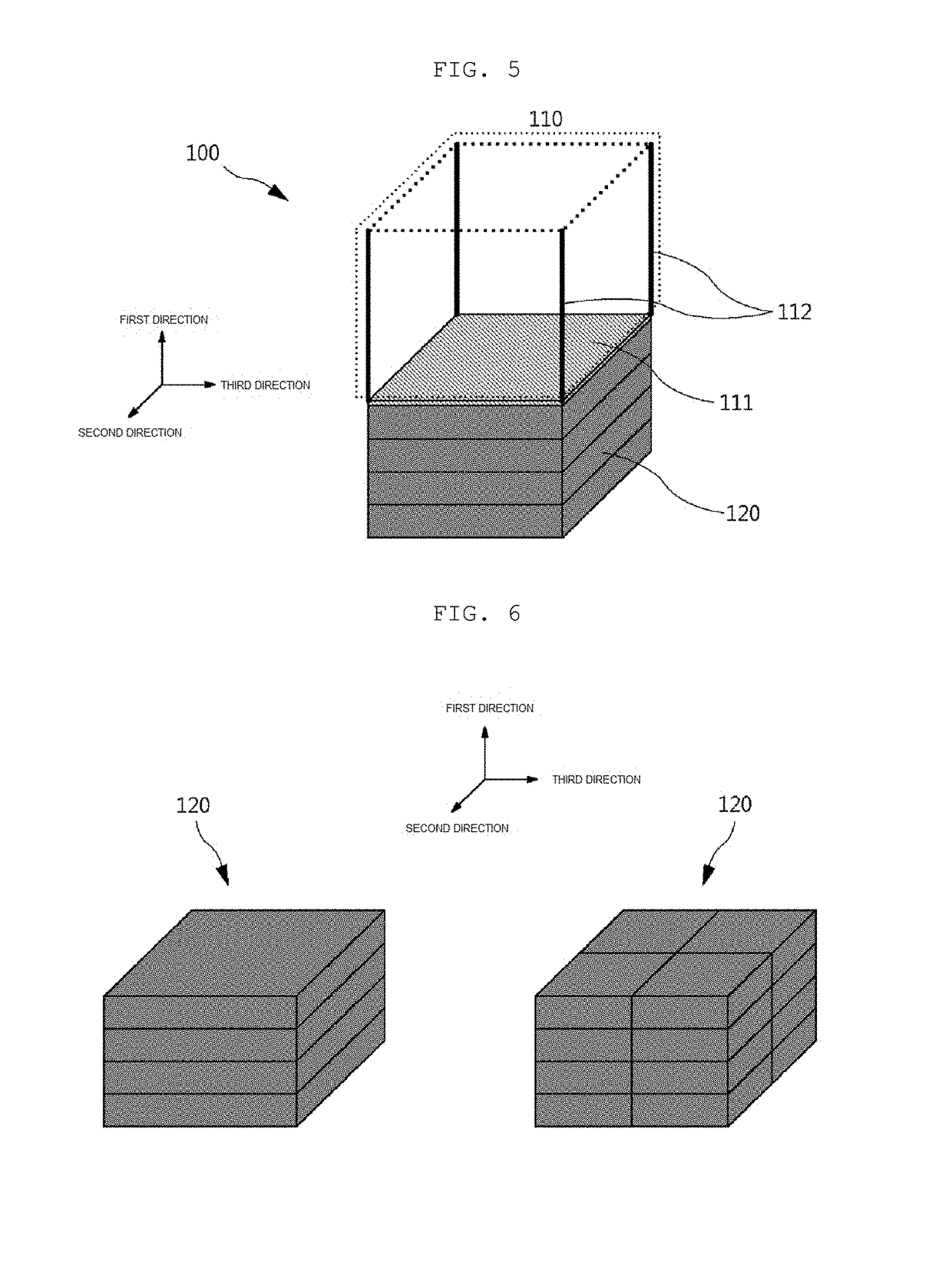
[0075]FIG. 12 shows one of application examples of the three-dimensional micro movement device according to the present invention. In a fused AFM microscope, the scan may also be performed by moving a stage on which an observation objection is disposed, but in performing a fine range of scan, there is a limitation in driving precision of the stage or a weight / large area sample may not be measured. Accordingly, a scanner for micro movement for separately moving only a microscope head is separately provided. However, according to the related art, since a one-dimensional scanner and a two-dimensional scanner are provided to be stacked, there are problems that a decrease in a resonance frequency and a deterioration of a scan speed limit due to an increase in an effective weight of the stacked scanner.

[0076]However, as shown in FIG. 12, if the three-dimensional micro movement device according to the present invention is applied as a three-dimensional scanner of the microscope head, the p...


PUM


Abstract

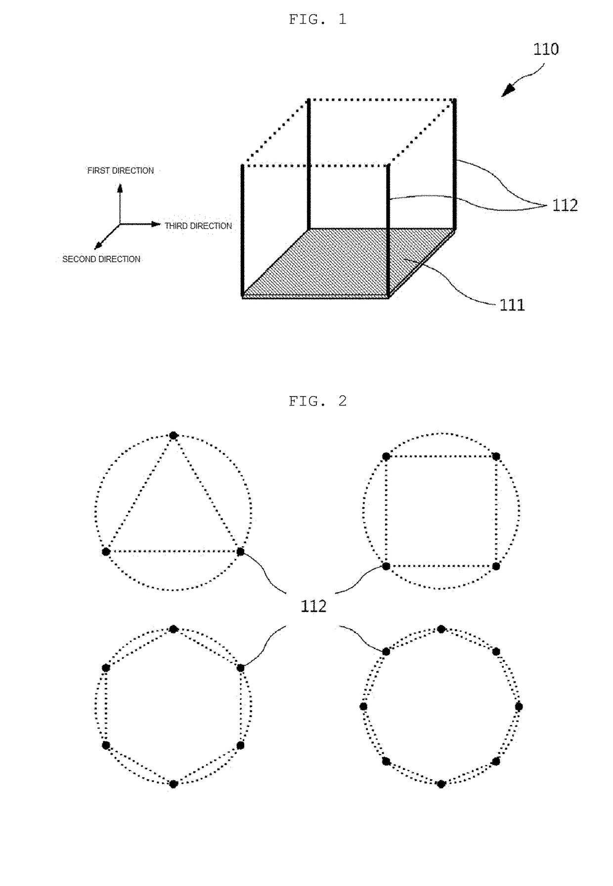
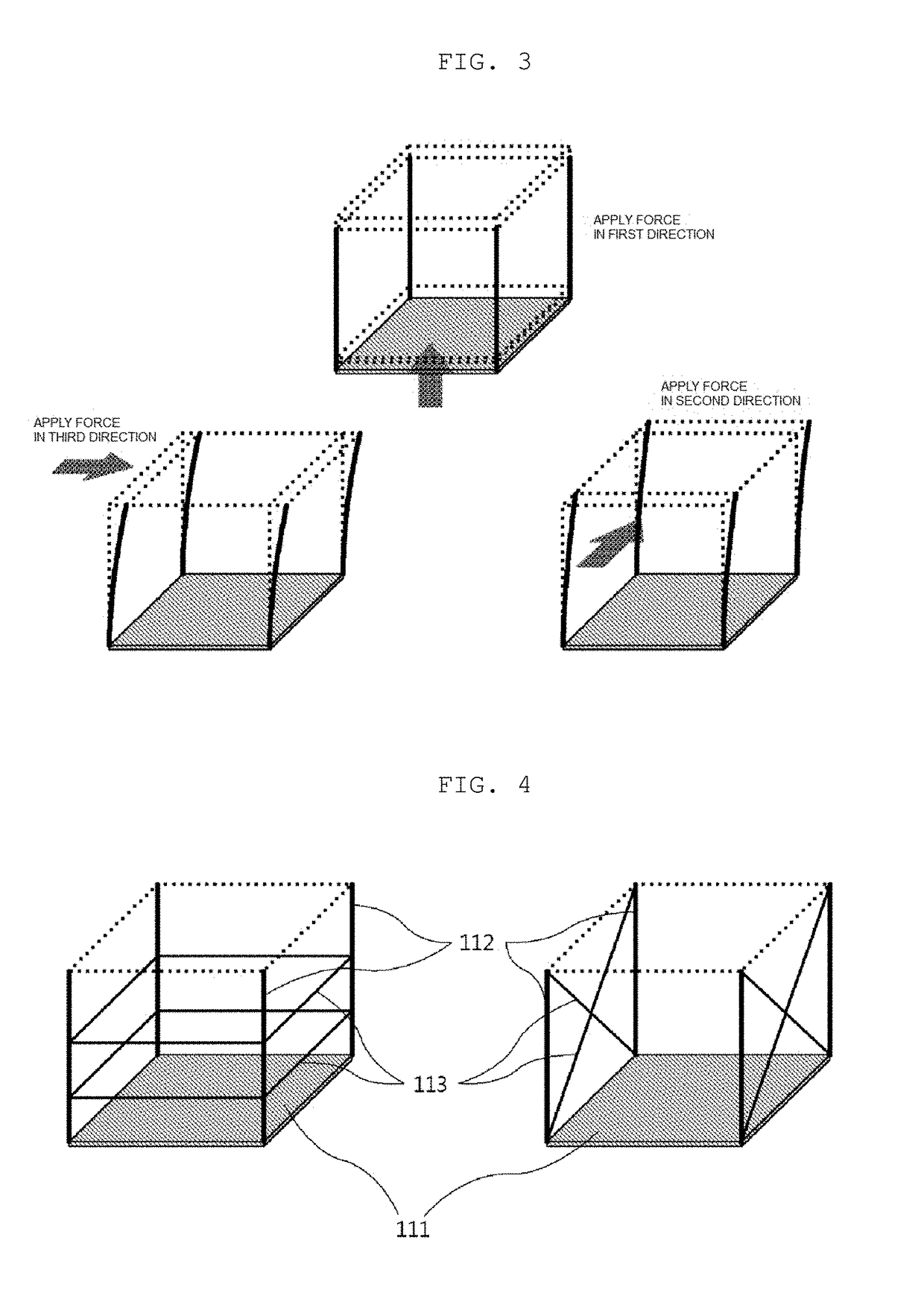
Provided is a linear structure for displacement transmission having a structure that enables a desired movement to be performed smoothly while minimizing complexity of a system through a simple structure in performing a precise and fine movement, and a one-dimensional and three-dimensional micro movement device using the same.

Description

TECHNICAL FIELD[0001]The present invention relates to a linear structure for displacement transmission and a one-dimensional and three-dimensional micro movement device using the same, and more particularly, to a linear structure for displacement transmission having a structure that enables a desired movement to be performed smoothly while minimizing complexity of a system through a simple structure in performing a precise and fine movement, and a one-dimensional and three-dimensional micro movement device using the same.[0002]In general, scanning microscopes such as an atomic force microscope (AFM), a scanning tunneling microscope (STM), and the like, electron / ion beam microscopes such as a scanning electron microscope (SEM) / focused ion beam (FIB) and the like, and micro machining devices such as a micro 3D printer and the like include a compact and lightweight head directly used for observation / machining, and a stage on which an object to be observed / machined is disposed. In this ...

Claims


Application Information

Patent Timeline
Patent Type & Authority Applications(United States)
IPC IPC(8): H01J37/20H02N2/02H02N2/04
CPCH01J37/20H02N2/026H02N2/028H02N2/043G01Q10/04G02B21/26H01J2237/20264
Inventor KIM, DAL HYUNPARK, BYONG CHONSHIN, CHAE HO
Owner KOREA RES INST OF STANDARDS & SCI
Learn More