Light emitting device, optical module comprising same device, and vehicle comprising same module
a technology of light emitting devices and optical modules, applied in the direction of semiconductor lasers, lighting and heating apparatus, television systems, etc., can solve the problems of increasing power consumption, achieve the effect of reducing the amount of space occupied, increasing freedom, and reducing power consumption for implementation
Active Publication Date: 2019-01-10
LG INNOTEK CO LTD
View PDF0 Cites 5 Cited by
- Summary
- Abstract
- Description
- Claims
- Application Information
AI Technical Summary
Benefits of technology
The invention is a light-emitting device that can be used in vehicles and other applications. It has several technical effects including reduced power consumption, smaller size, flexibility in positioning, increased efficiency, and suitability for a slimmer design. These effects make it easier to use and install the device while maintaining its performance.
Problems solved by technology
This increases power consumption and introduces limitations such as the requirement to provide a space for the movement of the optical system.
Method used
View moreImage
Smart ImageViewing Examples
Examples
Embodiment Construction
[0117]Various embodiments have been described in the best mode for carrying out the disclosure.
INDUSTRIAL APPLICABILITY
[0118]A light-emitting device and an optical module including the device according to the embodiments may be used in various fields such as domestic or industrial applications, vehicles, or various devices such as a display device or an indicator device.
Login to View More PUM
 Abstract
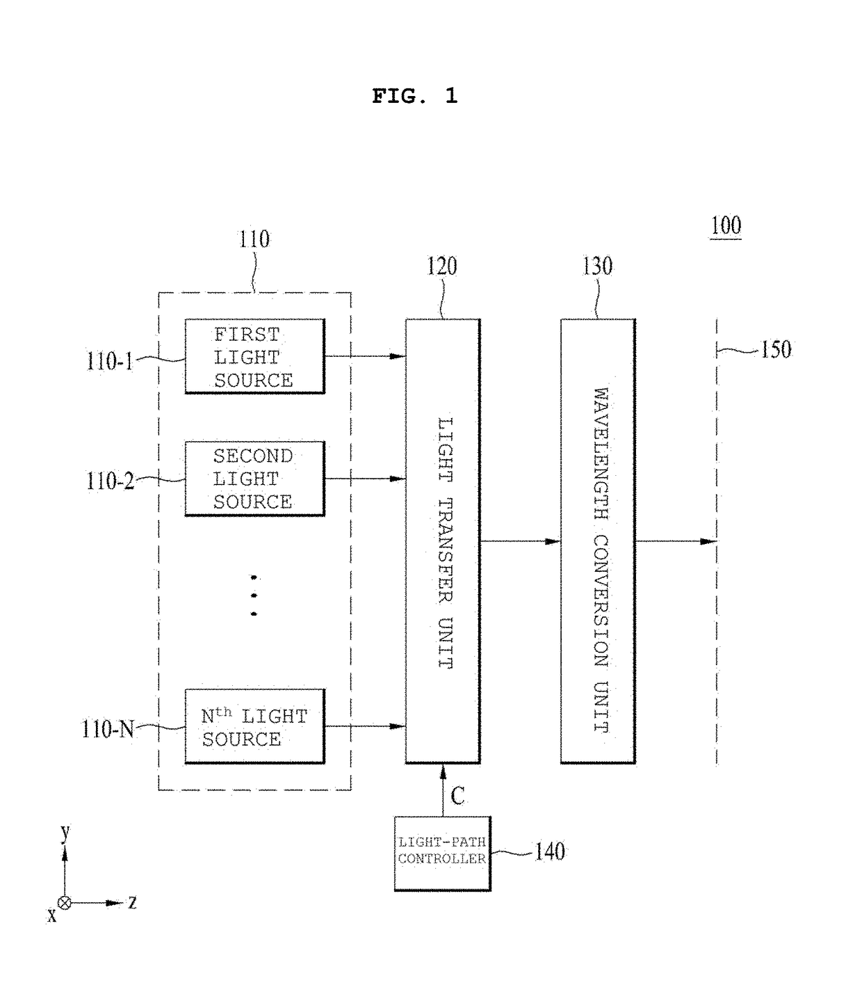
A light emitting device of an embodiment includes at least one light source; a wavelength conversion unit for converting the wavelength of excitation light so as to emit the excitation light having the converted wavelength as conversion light; a light transfer unit disposed on a light path between the at least one light source and the wavelength conversion unit for transferring the excitation light to the wavelength conversion unit; and a light-path controller moving at least a part of the light transfer unit so as to adjust at least one from among the direction and intensity of excitation light which enters the wavelength conversion unit.
Description
TECHNICAL FIELD[0001]Embodiments relate to a light-emitting device, an optical module including the device, and a vehicle including the module.BACKGROUND ART[0002]Light-emitting devices are widely used for domestic, industrial, and vehicular applications. For example, a light source of a light-emitting device used in a vehicular headlamp may be a halogen (or incandescent) bulb, a high-intensity discharge (HID) lamp, a xenon lamp, a light-emitting diode (LED), or the like. In addition, there is an increasing interest in a laser diode (LD) as a next-generation light source of a light-emitting device.[0003]Vehicular headlamps are becoming more advanced technologically, functionally, and aesthetically. Changes to light sources such that they have a reduced size while exhibiting the same energy efficiency and light output, material changes, precision injection and machining, and the like are driving this advancement. Such light sources are increased in brightness and reduced in size whil...
Claims
Login to View More Application Information
Patent Timeline
 Patent Type & Authority Applications(United States)
IPC IPC(8): F21S41/176F21K9/64F21S41/20F21S41/63F21S41/16F21S41/141F21K9/68F21K9/69F21S41/37F21K9/65B60Q1/00B60Q1/08H04N7/18B60Q1/14B60R1/00
CPCF21S41/176B60R2300/80F21S41/285F21S41/635F21S41/16F21S41/141F21K9/68F21K9/69F21S41/37F21K9/65B60Q1/0023B60Q1/085H04N7/183B60Q1/143B60R1/00F21Y2115/10F21Y2115/30F21W2102/13B60Q2300/112B60Q2300/12F21K9/64F21S41/675F21S41/365H01S5/4012H01S5/0071H01S5/0021H01S5/0617H01S5/06804H01S5/06808H01S5/06825H01S5/0683H05B47/10F21S41/14F21S41/36F21W2102/00G06V20/56F21S41/30F21S41/20F21S41/32
Inventor SON, CHANG GYUNKIM, KI CHEOLPARK, KANG YEOL
Owner LG INNOTEK CO LTD
Features
- R&D
- Intellectual Property
- Life Sciences
- Materials
- Tech Scout
- Unparalleled Data Quality
- Higher Quality Content
- 60% Fewer Hallucinations
Learn More Browse by: Latest US Patents, China's latest patents, Technical Efficacy Thesaurus, Application Domain, Technology Topic, Popular Technical Reports.
© 2025 PatSnap. All rights reserved.Legal|Privacy policy|Modern Slavery Act Transparency Statement|Sitemap|About US| Contact US: help@patsnap.com


