Load arrangement and electrical power arrangement for powering a load
- Summary
- Abstract
- Description
- Claims
- Application Information
AI Technical Summary
Benefits of technology
Problems solved by technology
Method used
Image
Examples
first embodiment
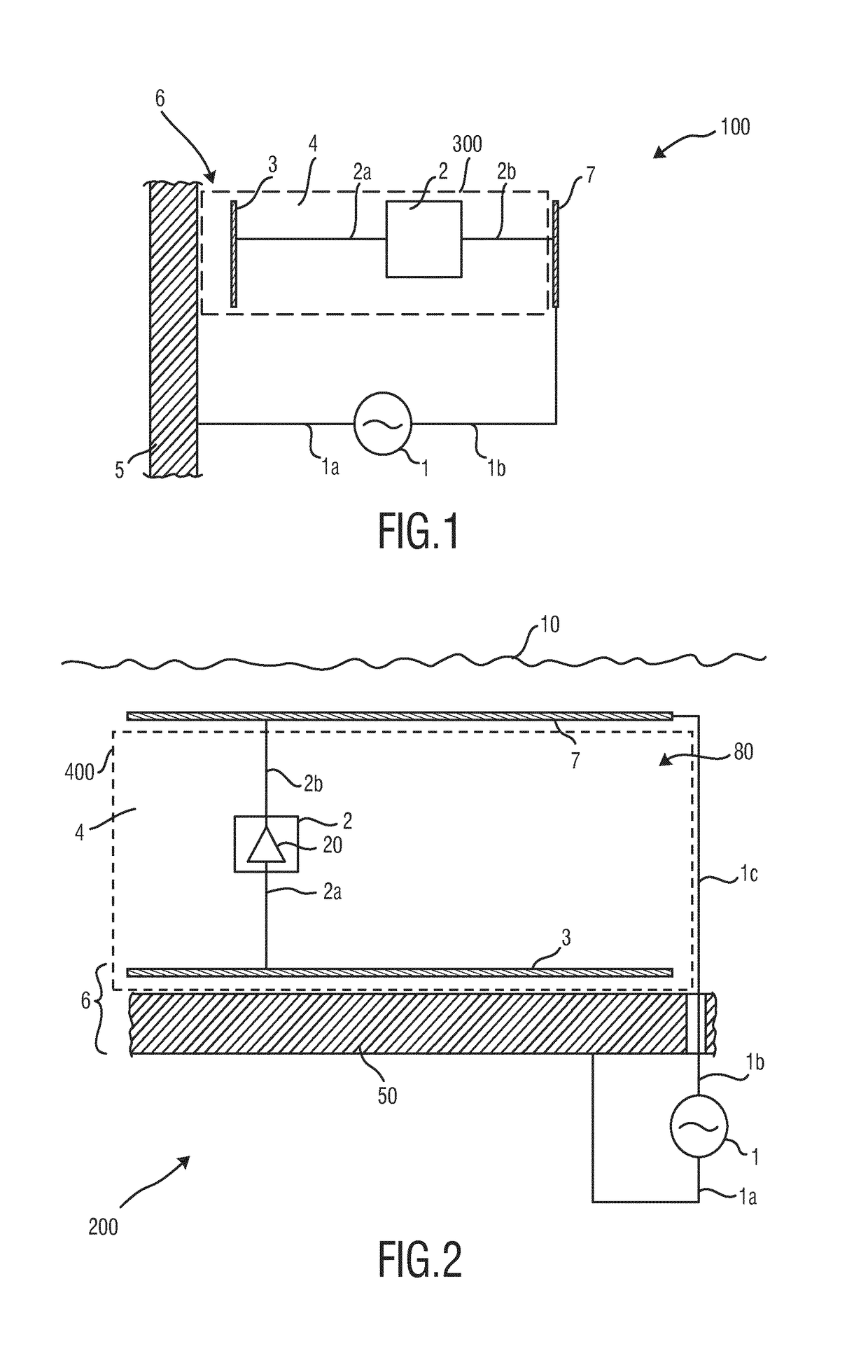
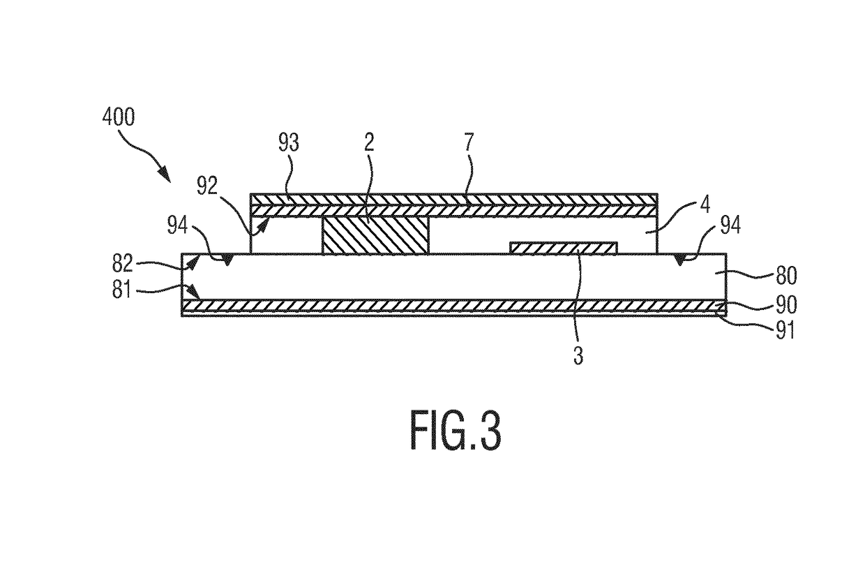
[0061]FIG. 2 shows a diagram of an electrical power arrangement 200 and a load arrangement 400 in an anti-fouling application scenario. In this embodiment, the load 20 is a UV-C LED and the first external element 50 is a ship hull, which is (at least partly) electrically conductive (i.e. the complete ship hull, only the inner surface, only the outer surface or only certain areas of the ship hull may be configured to be conductive or made from conductive material, e.g. a metal). The AC power source 1 is generally arranged on board of the ship. The first AC terminal 1a contacts the conductive surface of the ship hull 5, and the second AC terminal 1b is connected by a connection wire 1c through the ship hull 5 with the second electrode 7. The LED 20, the dielectric layer 4 and the first electrode 3 (optionally also the second electrode 7) are preferably carried by a carrier 80, which is arranged at the first external electrically conductive element (5, 50).
[0062]The load arrangement 40...
sixth embodiment
[0092]FIG. 13 shows a side view (FIG. 13A) and a top view (FIG. 13B) of a practical implementation of an electrical power arrangement 106 according to the present invention in an anti-fouling application scenario, which is similar to the sixth embodiment depicted in FIGS. 10 and 11. In this embodiment a single, thin and wide conductive power supply wire 3 (representing the first electrode) carried on top of one or more dielectric (adhesive) substrates 40 (part of which representing the dielectric layer 4) is provided, with the single supply wire 3 (being connect to the AC terminal 1b directly or by external member 11 (sea water)) preferably being executed in sheet aluminum and being voltage modulated by a high frequency AC oscillator (not shown). The single supply wire 3 is galvanically connected to a plurality of loads 25a, 25b, 25c connected in parallel, including for example local DC power sources executed in the form of a Graetz bridge 23 and LEDs 24 as shown in FIG. 9 or 12. Ea...
PUM
 Abstract
Description
Claims
Application Information
 - R&D
- Intellectual Property
- Life Sciences
- Materials
- Tech Scout
- Unparalleled Data Quality
- Higher Quality Content
- 60% Fewer Hallucinations
Browse by: Latest US Patents, China's latest patents, Technical Efficacy Thesaurus, Application Domain, Technology Topic, Popular Technical Reports.
© 2025 PatSnap. All rights reserved.Legal|Privacy policy|Modern Slavery Act Transparency Statement|Sitemap|About US| Contact US: help@patsnap.com


