Laser diode optical frequency modulation linearization algorithm

a technology of optical frequency modulation and linearization algorithm, which is applied in the direction of reradiation, instruments, and the details of semiconductor/solid-state devices

Active Publication Date: 2019-01-17
GM GLOBAL TECH OPERATIONS LLC
View PDF0 Cites 5 Cited by
  • Summary
  • Abstract
  • Description
  • Claims
  • Application Information

AI Technical Summary

Benefits of technology

[0014]In addition to one or more of the features described herein, the determining the pre-distortion of the drive signal includes determining a modulation voltage Vapp of the drive signal.
[0015]In addition to one or more of the features described herein, the determining the modulation voltage Vapp of the drive signal includes using the beat signal for feedback control, and the determining the modulation voltage Vapp of the drive signal includes determining the modulation voltage Vapp that results in a constant frequency of the beat signal.
[0016]In addition to one or more of the features described herein, the method also includes arranging a transmit beam steering device to direct the output signal out of the lidar system after collimation of the output signal from the transmit coupler by a transmit lens.
[0017]In addition to one or more of the features described herein, the method also includes arranging a receive lens to focus the received signal directed by a receive beam steering device to the receive coupler.

Problems solved by technology

However, that approach is costly.

Method used


Image

  • Laser diode optical frequency modulation linearization algorithm
  • Laser diode optical frequency modulation linearization algorithm
  • Laser diode optical frequency modulation linearization algorithm

Examples


Embodiment Construction

[0029]The following description is merely exemplary in nature and is not intended to limit the present disclosure, its application or uses. It should be understood that throughout the drawings, corresponding reference numerals indicate like or corresponding parts and features.

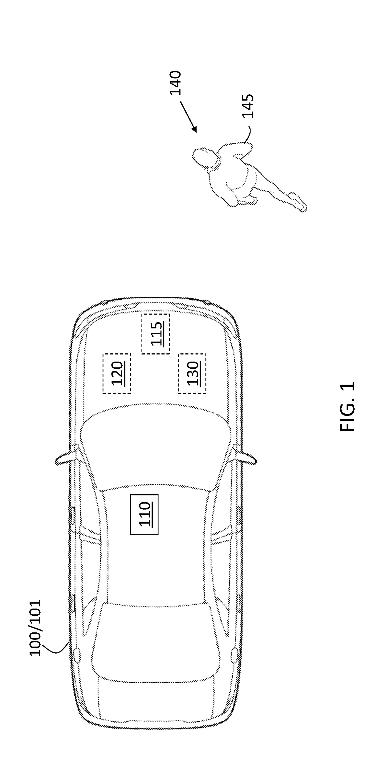
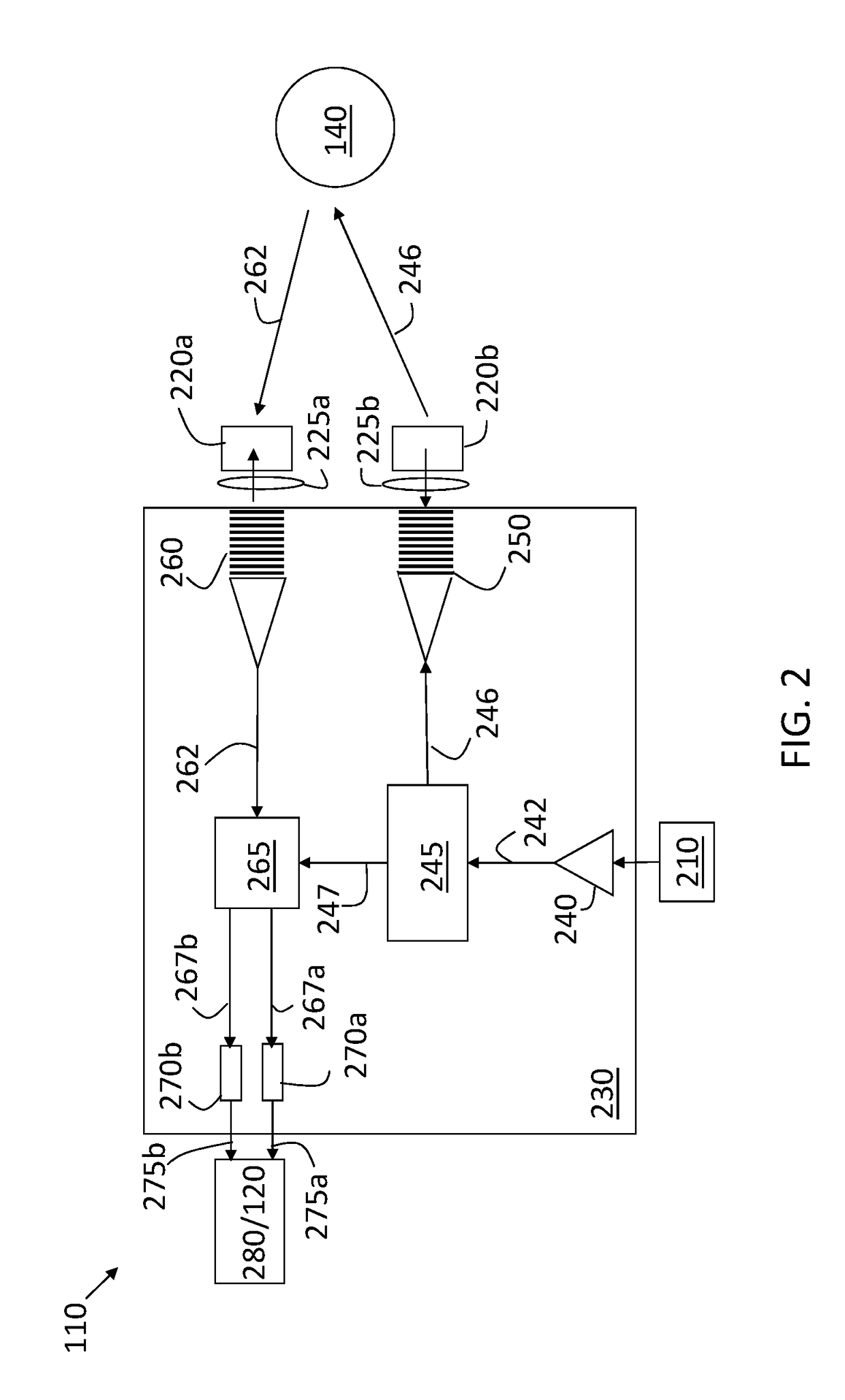
[0030]As previously noted, a coherent lidar system transmits an FMCW signal. In a chip-scale lidar system, the FMCW signal may be obtained by controlling the drive current applied to a laser diode. However, the modulation of the drive current does not correspond exactly with the resulting frequency modulation of the continuous wave output by the laser diode. That is, a linear variation in the drive current results in a nonlinear optical frequency modulation of the signal output by the laser diode. This nonlinearity in the FMCW signal results in a reduced signal-to-noise ratio (SNR) and, consequently, a loss in performance of the lidar system.

[0031]Embodiments of the systems and methods detailed herein relate to...


PUM


Abstract

A lidar system includes a laser diode to provide a frequency modulated continuous wave (FMCW) signal, and a current source to provide a drive signal that modulates the laser diode. The current source is controlled to pre-distort the drive signal to provide a linear FMCW signal. The lidar system also includes a splitter to split the FMCW signal into an output signal and a local oscillator (LO) signal, a transmit coupler to transmit the output signal, a receive coupler to obtain a received signal based on reflection of the output signal by a target, and a combiner to combine the received signal with the LO signal into first and second combined signals. A first and second photodetector respectively receive the first and second combined signals and output first and second electrical signals from which a beat signal that indicates the pre-distortion needed for the drive signal is obtained.

Description

CROSS-REFERENCE TO RELATED APPLICATIONS[0001]This application claims the benefit of priority of U.S. Provisional Application No. 62 / 531,414 filed Jul. 12, 2017, the disclosure of which is incorporated herein by reference in its entirety.INTRODUCTION[0002]The subject disclosure relates to a laser diode optical frequency modulation linearization algorithm.[0003]Vehicles (e.g., automobiles, trucks, construction equipment, farm equipment, automated factory equipment) are increasingly outfitted with sensors that provide information to augment or automate vehicle operation. Exemplary sensors include radio detection and ranging (radar) systems, cameras, microphones, and light detection and ranging (lidar) systems. An exemplary lidar system is a coherent lidar system that transmits a frequency modulated continuous wave (FMCW) signal and relies on optical coherence between the transmitted signal and a return signal resulting from reflected scattering of the transmitted signal by a target to ...

Claims


Application Information

Patent Timeline
Patent Type & Authority Applications(United States)
IPC IPC(8): G01S17/32G01S7/491G01S17/93G01S7/4911G01S7/4913G01S7/4914G01S17/02G01S17/34G01S17/86G01S17/931
CPCG01S17/325G01S17/936G01S7/4913G01S7/4817G02B27/28G01S17/42G01S7/4815G01S7/4911G01S17/58G01S7/4816G01S17/34G01S17/931G01S17/86G01S7/499G01S17/02G02B6/122G02B6/2766G02B6/4209G02B2006/0098H01L23/544H01L31/02327H01L31/16H01L2223/54426H01L2223/54486G01S17/003G01S17/32G01S7/4914G01S7/491G01S7/4972B81B7/02B81B2207/03G01S7/4818G02B27/30H01S5/125
Inventor SARKISSIAN, RAYMONDSAYYAH, KEYVAN
Owner GM GLOBAL TECH OPERATIONS LLC
Why Eureka
Try Eureka