
Liquiefying a gaseous medium

a gaseous medium and arrangement technology, applied in the direction of lighting and heating equipment, container filling under pressure, discharging methods, etc., can solve the problems of changing the return temperature, affecting the efficiency of the liquefaction plant, and taking a long time to cool down the tank sufficiently, so as to reduce the proportion of liquid helium directly exiting the return line, the cooling effect of the storage tank is great, and the cooling phase of the start-up operation is reduced.

Active Publication Date: 2019-01-31
LINDE AG
View PDF5 Cites 3 Cited by
  • Summary
  • Abstract
  • Description
  • Claims
  • Application Information

AI Technical Summary

Benefits of technology

The invention is about a new method for cooling a storage tank used in a liquefaction plant. The method involves using cold gas to cool the tank before the liquid medium is introduced. This results in a more stable operation of the liquefaction plant and reduces the risk of activating the pressure safety system of the tank. The invention also prevents the introduction of heat from the transfer lines to be cooled into the storage tank during the cooling phase, which leads to a higher efficiency of the cooling process.

Problems solved by technology

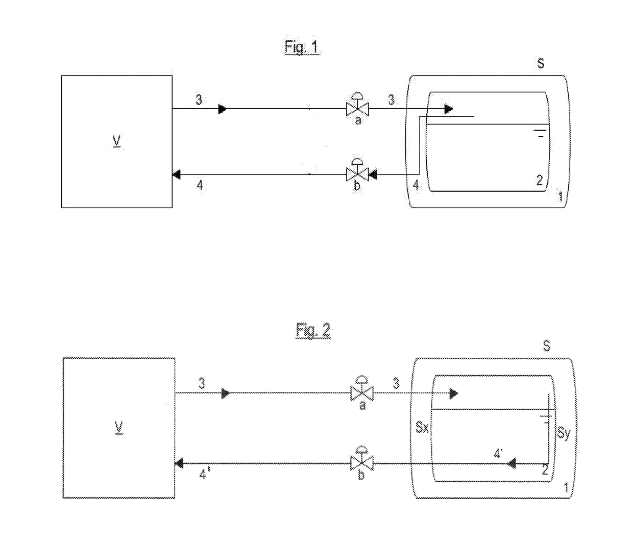
In this known arrangement, the two transfer lines are arranged at the same side of the storage tank as shown in FIG. 1, and this can cause problems in the start-up and normal operation of the apparatus.
When the gaseous helium is sent back to a liquefaction plant, changes in the return temperature can have a negative effect on the efficiency of the liquefaction plant.
In other words, the cold gaseous helium does not remain in the storage tank for any significant time, and this means it can take a long time to cool the tank down sufficiently.

Method used


Image

  • Liquiefying a gaseous medium
  • Liquiefying a gaseous medium

Examples


Embodiment Construction

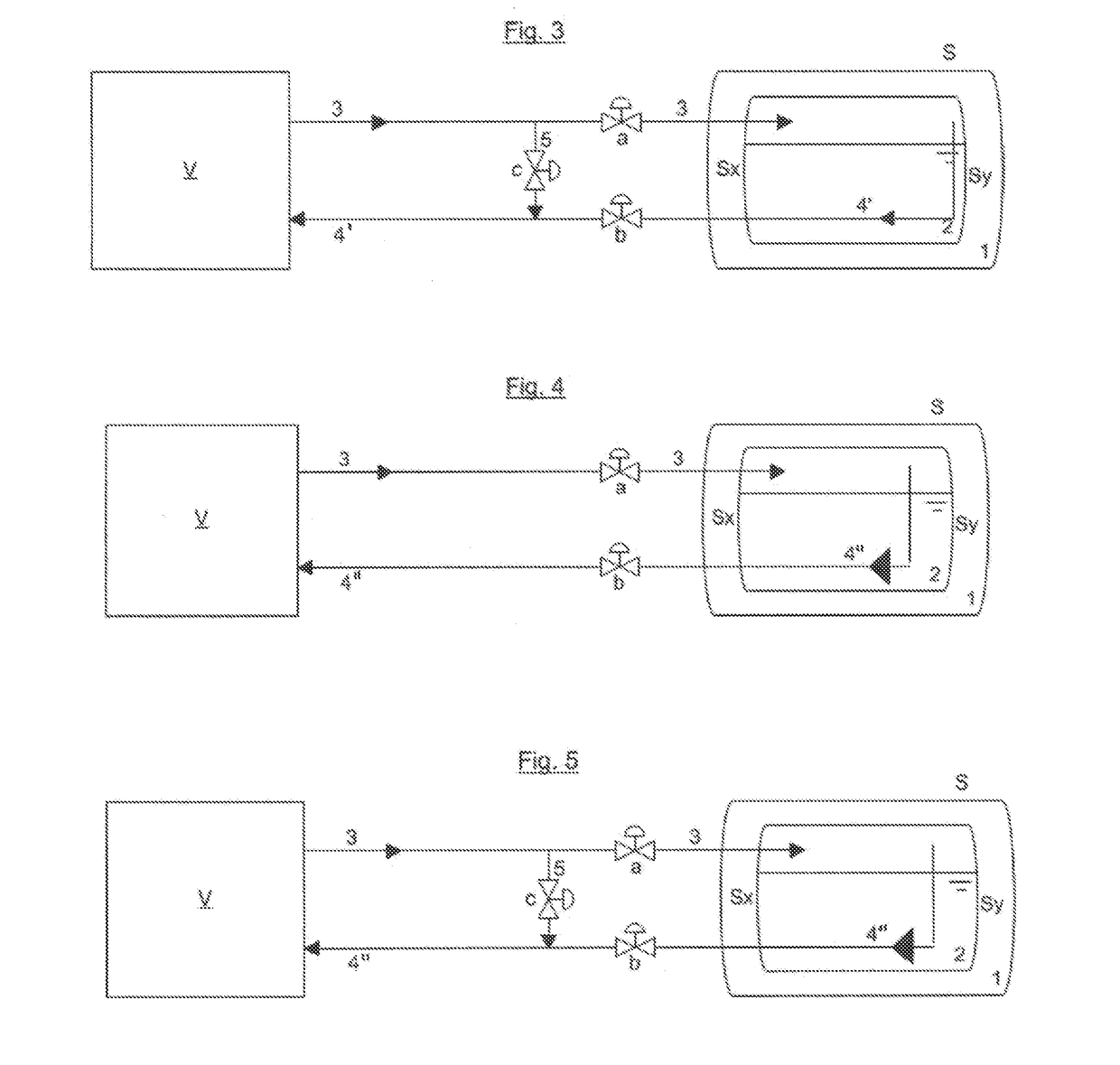
[0047]The figures each show a liquefaction plant V represented simply as a black box, as well as a diagrammatically represented storage tank S. In general, said storage tank comprises an outer tank 1 as well as an inner tank 2, wherein the clearance between inner tank and outer tank is designed to be vacuum insulated.

[0048]FIGS. 2 to 5 show various embodiments of invention which all provide an improved operation over the previously known arrangement described above. In FIGS. 2 to 5 similar components are given the same reference numerals as in FIG. 1.

[0049]In FIG. 2, it will be noted that the second (return) transfer line 4′, which is used for transferring the medium from the storage tank S into the liquefaction plant V, has a different configuration. In FIG. 2, an outlet of the first transfer line 3 into the storage tank S is provided adjacent to a first side wall, Sx, of the tank S and an inlet of the second transfer line is provide adjacent to a second side wall, Sy, the second s...


PUM


Abstract

An arrangement comprising at least one liquefaction plant for liquefying a gaseous medium to produce a liquefied medium; and at least one storage tank for storing the liquefied medium. A first transfer line is provided which is connected between the liquefaction plant and the storage tank, for transferring liquefied medium from the liquefaction plant into the storage tank. A second transfer line is connected between the liquefaction plant and the storage tank, for transferring gaseous medium from the storage tank into the liquefaction plant. The second transfer line, which used for transferring medium from the storage tank into the liquefaction plant, is arranged so that it is routed at least partially through the area of the storage tank in which the liquefied medium is stored in use.

Description

FIELD OF THE INVENTION[0001]The invention relates to an arrangement for liquefying a gaseous medium having at least one storage tank used for storing the liquefied medium. The invention further relates to a method for cooling the transfer lines prior to use.BACKGROUND OF THE INVENTION[0002]The term “liquefaction plant” is understood to mean any plant or any process that is used for cooling and liquefying a gaseous medium, for example, hydrogen, a noble gas such as helium, neon, etc., oxygen, nitrogen, or a hydrocarbon mixture, in particular natural gas.[0003]In known arrangements, there is provided at least one liquefaction plant for liquefying a gaseous medium and at least one storage tank which is used to store the liquefied medium. Generally, two transfer lines are provided which connect the liquefaction plant and the storage tank. A first transfer line is used to transfer the liquefied medium from the liquefaction plant to the storage tank, and a second transfer line (a return l...

Claims


Application Information

Patent Timeline
Patent Type & Authority Applications(United States)
IPC IPC(8): F17C13/04F17C3/08F17D1/08
CPCF17C13/04F17C3/08F17D1/082F17C2221/012F17C2221/016F17C2221/033F17C2221/011F17C2221/014F17C2260/031F17C2205/0323F17C2205/0355F17C2205/0388F17C2227/04F17C2225/013F17C2223/0123F17C2223/043F17C2225/043F25J1/0005F25J1/0007F25J1/001F25J1/0015F25J1/0017F25J1/0022F25J1/004F25J1/0247F25J2215/32F25J2245/02F25J2245/90F25J2290/62Y02E60/32F17C5/02F17C7/02F25J1/00
Inventor DACHAUER, CHRISTIANWILHELM, HANSPETERKELLER, LUKAS
Owner LINDE AG
Learn More