Few mode optical fibers for mode division multiplexing

Active Publication Date: 2019-01-31
DRAKA COMTEQ BV
View PDF0 Cites 13 Cited by
  • Summary
  • Abstract
  • Description
  • Claims
  • Application Information

AI Technical Summary

Benefits of technology

[0058]By properly choosing the respective lengths Li of all optical fibers constituting the optical link, it is possible to build a few-mode optical fiber link, which allow guiding an increased number of LP modes as compared to prior art FMFs, while reaching the lowest Differential Mode Group Delay. Such an optical link is hence a DMGD-compensated FMF link and may show improved properties over the individual FMFs comprised in said optical link. Such low DMGD allow all modes being simultaneously detected using 2N×2N (N being the total number of spatial m

Problems solved by technology

However, single-mode fibers suffer from nonlinearity problems, which are major limitations on fiber transmission capacity.
This optimization, however, becomes more and more difficult when the number of LP modes increases.
Actually, a severe degradation of the bend losses prevents the use of the 9th and 10th mode groups in space-division-multiplexed systems for such fibers.
Undesired modes have respective effective indices

Method used


Image

  • Few mode optical fibers for mode division multiplexing
  • Few mode optical fibers for mode division multiplexing
  • Few mode optical fibers for mode division multiplexing

Examples


Embodiment Construction

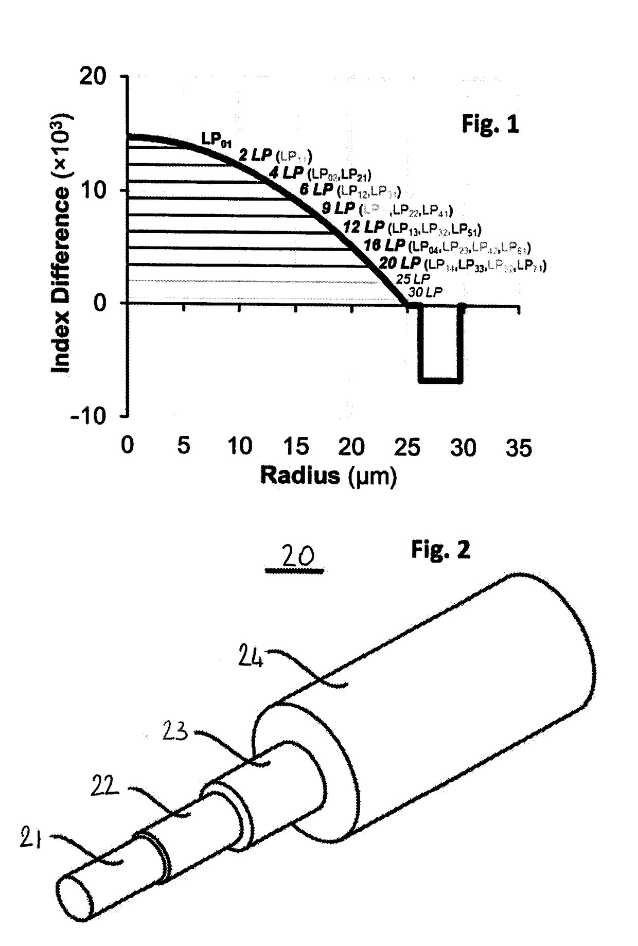
[0082]The general principle of the present disclosure is to propose a carefully designed trench-assisted graded index few-mode optical fiber, showing reduced Differential Mode Group Delay and supporting more LP modes over prior art FMFs. More precisely, the purpose of such a design is to optimize the interface between the graded-index core and the trench, in order to increase the number of supported LP modes up to 25 or 30, while keeping the Differential Mode Group Delay between any combination of LP guided modes low, preferably below 200 ps / km, and while keeping the bend loss of any LP guided modes low, preferably below 100 dB / turn at 10 mm bend radius.

[0083]Light travelling in an optical fiber actually forms hybrid-type modes, which are usually referred to as LP (linear polarization) modes. The LP0p modes have two polarization degrees of freedom and are two-fold degenerate, the LPmp modes with m≥1 are four-fold degenerate. These degeneracies are not counted when designating the nu...


PUM


Abstract

Few mode optical fibers for mode division multiplexing. The Few Mode Fiber supporting 25 or 30 LP guided modes and includes a graded index core with a α-profile, a radius R1 (at 0 refractive index difference) between 21.5 and 27 μm and a maximum refractive index difference Dn1 between 12.5×10⁻³ and 20×10−3, and an end of the α- profile at a radius R1b, with index difference Dn1b; a trench surrounding the core with radius R3 between 30 and 42 μm and refractive index difference Dn3 between −15.10−3 and −6.10−3, an intermediate depressed trench with a radius R2, with R1b<R2<R3 and a refractive index difference Dn2, with Dn3<Dn2<0, wherein: for |Dn1b−Dn2|>=0.5×10⁻³, Min(Dn1b, Dn2)≤−1.5×10⁻³, and for |Dn1b−Dn2|<0.5×10⁻³, Dn2 is between −5×10⁻³ and −3.5×10⁻³.

Description

1. FIELD OF THE INVENTION[0001]The present disclosure relates to the field of fiber optic transmission, and, more specifically, to improved few-mode fiber designs for mode division multiplexing.2. BACKGROUND[0002]An optical fiber is conventionally constituted of an optical core, which transmits an optical signal, and of an optical cladding, which confines the optical signal within the optical core. To that end the refractive index of the core, n0, is greater than the one of the cladding, ncl. An optical fiber is generally characterized by a refractive index profile that associates the refractive index (n) with the radius (r) of the optical fiber: the distance r with respect to the center of the optical fiber is shown on x-axis and the difference Dn between the refractive index at radius r, n(r), and the refractive index of the optical cladding ncl is shown on y-axis.[0003]Nowadays, two main categories of optical fibers exist: multimode fibers and single-mode fibers. In a multimode f...

Claims


Application Information

Patent Timeline
IPC IPC(8): G02B6/028G02B6/036H04J14/04
CPCG02B6/0288G02B6/03638H04J14/04G02B6/0365
Inventor SILLARD, PIERREMOLIN, DENISBIGOT, MARIANNE
Owner DRAKA COMTEQ BV
Why Eureka
Try Eureka